


19
Gas Pressure
Correct gas pressure is essential for efficient and safe
operation of the GF 400 DV Sebago gas stove. It is
important that the correct pressure is established at
the time of the installation. Proper gas pressure
provides a consistent flow of gas to the appliance and
is instrumental in checking for gas leaks.
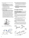
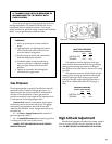
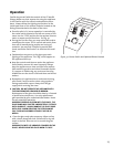
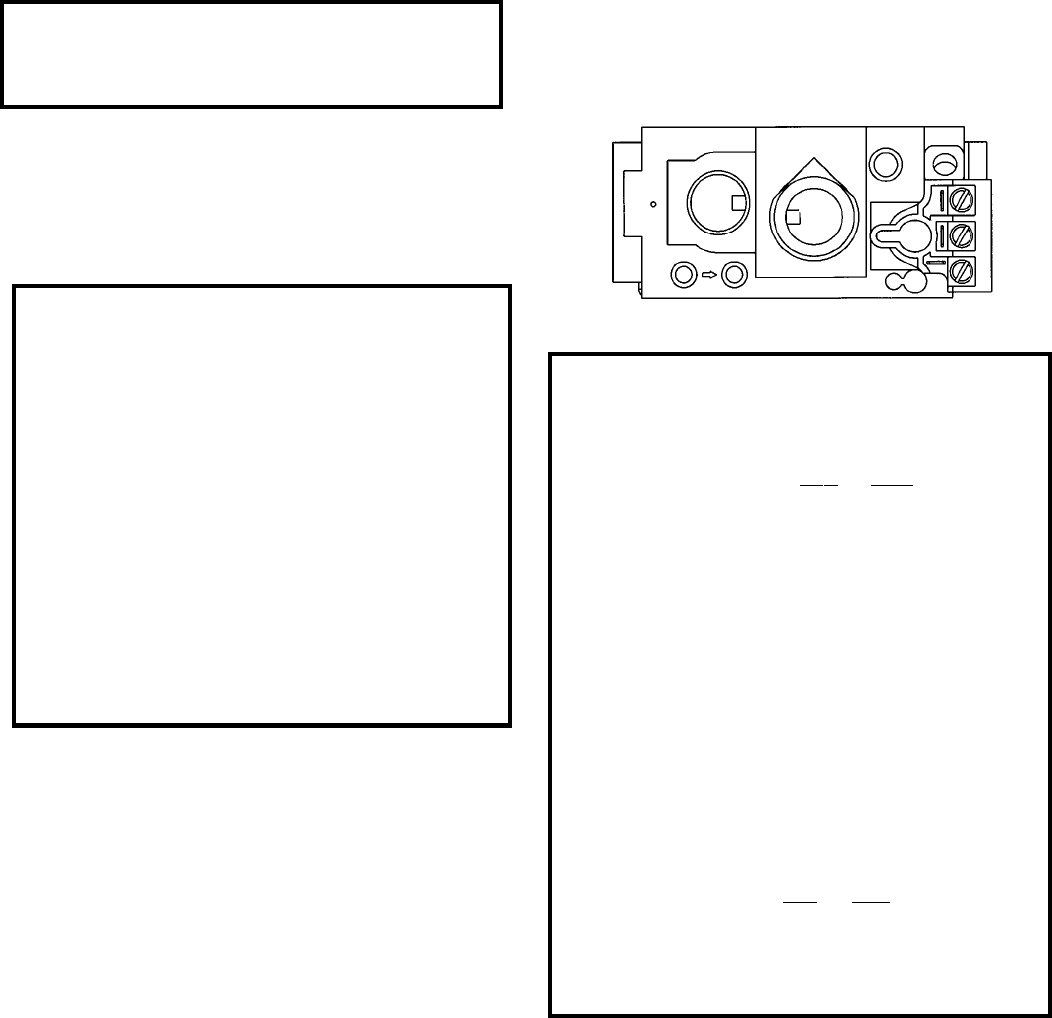
Pressure Test: Attach a manometer to the appro-
priate test point on the valve. See fig. 28. The gauge
connections are located on the front of the valve
under the On/Off/Pilot- knob. Gauge connections are
identified by:
E - for Inlet or Supply Pressure (the amount of
gas coming to the valve.)
A - for Manifold Pressure (the amount of gas that
is coming out of the valve to the burner.)
ALWAYS TEST PRESSURES WITH VALVE CONTROL
KNOB SET ON HIGH.
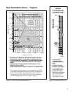
High Altitude Adjustment
Installations located at altitudes from 2000 - 4500 ft.
(610 m -1370 m) DO NOT require adjustment for alti-
tude. DO NOT DERATE THIS APPLIANCE FOR ALTITUDE.
Figure 28. Pressure test points.
E
A
Leak test:
1. Mix a 50-50 solution of water and dish
soap.
2. Light appliance- see lighting instructions
on the inside back cover of this manual
or on the stove’s rating plate.
3. Brush or spray all joints and connections
with the soapy water solution.
4. If bubbles appear at any connection or
seam or a gas odor is detected, immedi-
ately turn gas control knob to the OFF
position.
5. Tighten or reconnect the leaking joint
and retest for any gas leaks.
A T-HANDLE GAS COCK IS REQUIRED IN
MASSACHUSETTS TO COMPLY WITH
CODE 248CMR.
Secure all joints tightly using appropriate tools and
sealing compounds. For propane units be sure to use
compounds that are propane resistant. Turn on gas
supply and test for gas leaks using a soapy water solution.
Never use an open flame to check for leaks.
INLET GAS PRESSURES
(inches water column)
MIN MAX
NATURAL GAS 5.0 7.0
PROPANE 12.0 14.9
The appliance and its appliance main gas
valve must be disconnected from the gas supply
piping system during any pressure testing on
that system at test pressures in excess of 1/2 psig
(3.5 kPa).
The appliance must be isolated from the gas
supply line by closing its individual manual gas
shut-off valve (gas cock) during any pressure
testing of the gas supply piping system that is
equal to or exceeds pressures of 1/2 psig (3.5
kPa).
MANIFOLD PRESSURES
(inches water column)
MIN MAX
NATURAL GAS 1.2 3.8
PROPANE 2.9 11.0