


17
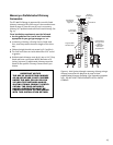
Close
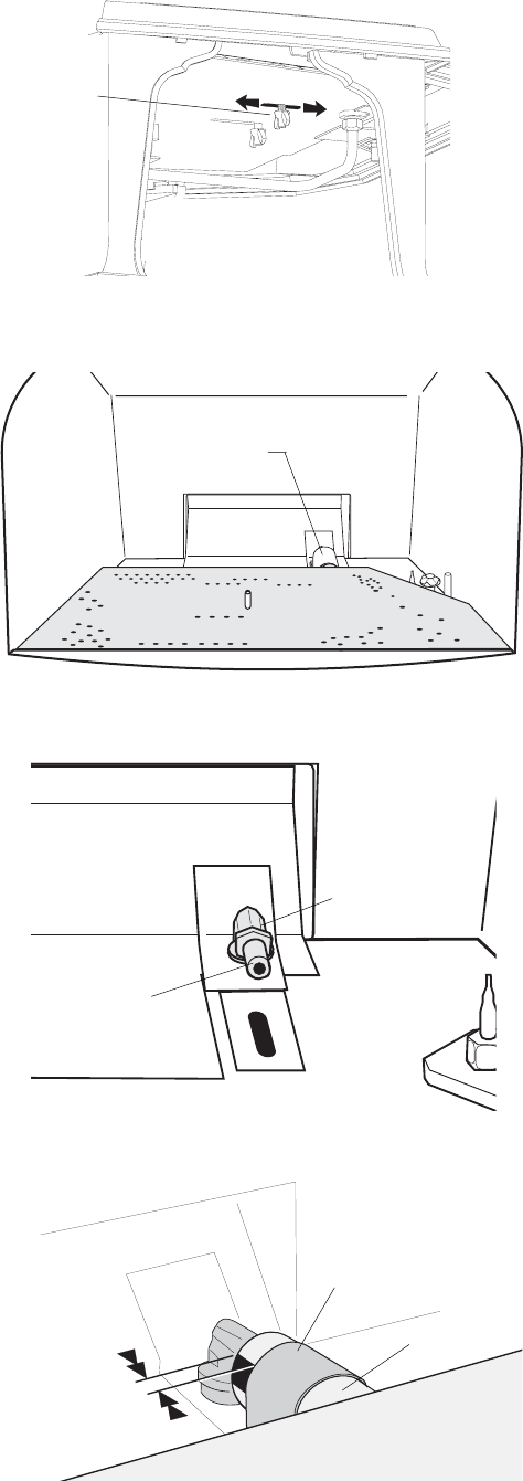
Open
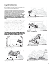
Fuel Conversion Procedure
Refer to fig. 47, Illustrated Parts Breakdown, to identify
part numbers below.
1. Turn off gas supply to stove.
2. Remove the stove Top Plate (41).
3. Disengage the two Glass Frame Latches at the top of
the firebox. See illustration on page 5. Carefully lift
the glass panel up and out of the stove.
4. If installed, remove the Embers and Log Set using care
not to damage the fragile log parts.
5. Lift out the Burner Skirt (33). Tilt the skirt at an angle
to clear the firebox sides and front.
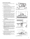
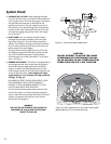
6. Reach under the stove and remove the Air Shutter
wingnut from its stud. As you face the right side, it is
the one closest to you. See fig. 21.
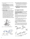
7. Lift out the Burner Plate: NOTE: There are no screws
securing the Burner to the floor of the firebox. Pull the
Air Shutter forward and lift the burner together with
shutter up and out of the stove as a unit. See fig. 22.
8. Change the Main Burner Orifice. See fig. 23. Using a
½” open ended wrench or deep-well socket remove
the burner orifice from its brass elbow housing and
replace with the appropriate orifice supplied in the kit.
#33 for NG
1.65 mm for LPG
9. Replace the Air Shutter with its gasket and push it all
the way back to allow replacement of the Burner
Plate.
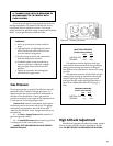
10. Replace the Burner Plate. Engage the Air Inlet Tube
with the Air Shutter and burner orifice. Properly seated,
the burner plate will be engaged at its front corners
with the two support brackets located at the front of
the firebox.
• Replace the wingnut loosely on the air shutter stem
under the stove. Air shutter adjustment will be done last.
11. CHANGE THE PILOT ORIFICE: From within the firebox,
remove the Pilot Head by pulling it straight up from
the pilot base. See fig. 25.
Using the 4 mm allen wrench that is included with
the conversion kit, unscrew the pilot orifice (counter-
clockwise). Replace with the appropriate orifice:
# 51 for natural gas
#30 for propane gas
12. Tighten orifice into the base of the pilot assembly. To
prevent bypass leaks, be sure the orifice is secured
tightly and flush with the base. Replace pilot head by
pushing it down onto the pilot base.
13. Replace the Variable Regulator. Using a Torx T-20
screwdriver, remove the three screws from the front
of the valve regulator. See fig. 26.
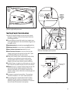
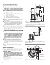
Figure 21. Locate and remove the Air Shutter wingnut
from under the right side of the stove.
Figure 22. Remove the Air Shutter and Burner as a unit.
Burner Plate
Air Shutter
Figure 23. Change the Burner Orifice.
Burner
Orifice
Brass Elbow
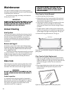
Figure 24. Air Shutter Setting
Air Shutter
Opening
Dimension
Air
Shutter
Wingnut
Burner Plate
Air Inlet
Tube
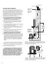
FRONT
LEG
BACK
LEG