


364861-UIM-B-0708
Johnson Controls Unitary Products 7
DOWNFLOW DUCT CONNECTORS
All downflow installations must use a suitable duct connector approved
by the furnace manufacturer for use with this furnace. The duct connec-
tors are designed to be connected to the rectangular duct under the
floor and sealed. Refer to the instructions supplied with the duct con-
nector for proper installation. Refer to the separate accessory parts list
at the end of these instructions for the approved accessory duct con-
nectors.
RESIDENTIAL AND MODULAR HOME UPFLOW
RETURN PLENUM CONNECTION
Return air may enter the furnace through the side(s) or bottom depend-
ing on the type of application. Return air may not be connected into the
rear panel of the unit.
BOTTOM RETURN AND ATTIC INSTALLATIONS
Bottom return applications normally pull return air through a base plat-
form or return air plenum. Be sure the return platform structure or return
air plenum is suitable to support the weight of the furnace.
The internal bottom panel must be removed for this application.
Attic installations must meet all minimum clearances to combustibles
and have floor support with required service accessibility.
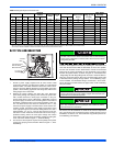
HORIZONTAL APPLICATION
ATTIC INSTALLATION
This appliance is certified for line contact when the furnace is installed
in the horizontal left or right position. The line contact is only permissible
between lines that are formed by the intersection of the top and two
sides of the furnace and the building joists, studs or framing. This line
may be in contact with combustible material. Refer to Figure 10, "Typi-
cal Attic Installation".
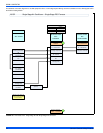
SUSPENDED FURNACE / CRAWL SPACE
INSTALLATION
The furnace can be hung from floor joists or installed on suitable blocks
or pad. Blocks or pad installations shall provide adequate height to
ensure the unit will not be subject to water damage. Units may also be
suspended from rafters or floor joists using rods, pipe angle supports or
straps. Angle supports should be placed at the supply air end and near
the blower deck. Do not support at return air end of unit. All four sus-
pension points must be level to ensure quite furnace operation. When
suspending the furnace use a secure platform constructed of plywood
or other building material secured to the floor joists. Refer to for typical
crawl space installation.
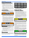
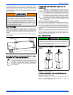
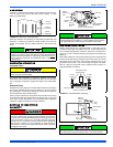
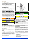
FIGURE 8: Combustible Floor Base Accessory
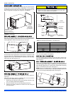
FIGURE 9: Horizontal Application
This furnace may be installed in a horizontal position on either side
as shown above. It must not be installed on its back.
FURNACE
WARMAIR PLENUM
WITH 1” FLANGES
FIBERGLASS
INSULATION
FIBERGLASS TAPE
UNDER FLANGE
COMBUSTIBLE FLOOR
BASEACCESSORY
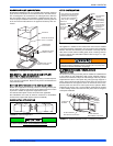
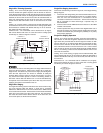
FIGURE 10: Typical Attic Installation
When a furnace is installed in an attic or other insulated space,
keep all insulating materials at least 12 inches (30.5 cm) away from
furnace and burner combustion air openings.
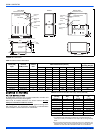
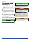
FIGURE 11: Typical Suspended Furnace / Crawl Space Installation
Return
Air
Sediment
Trap
GasPiping
Supply
Air
Vent (Maintain
required
clearances to
combustibles)
Line contact only permissible
between lines formed by the
intersection of furnace top
and two sides and building
joists, studs or framing
12”
30”MIN.
WorkArea
Filter rack
must be a minimum
distance
of 18” (45.7 cm)
from the
furnace
12”
Sheet metal in
front of furnace
combustion air
Openings is
Recommended
Angle Iron
Bracket
6” Min. Between
Rod & Front of Furnace
1” Max. Between
Rod & Back of Furnace
Support
Bracket