


364861-UIM-B-0708
Johnson Controls Unitary Products 5
On all installations without a coil, a removable access panel is recom-
mended in the outlet duct such that smoke or reflected light would be
observable inside the casing to indicate the presence of leaks in the
heat exchanger. This access cover shall be attached in such a manner
as to prevent leaks.
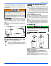
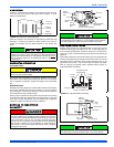
DUCT FLANGES
Four flanges are provided to attach ductwork to the furnace. These
flanges are rotated down for shipment. In order to use the flanges,
remove the screw holding an individual flange, rotate the flange so it is
in the upward position and reinstall the screw then repeat this for all 4
flanges.
If the flanges are not used, they must remain in the rotated down posi-
tion as shipped.
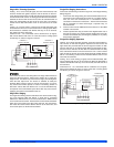
DUCTWORK INSTALLATION AND SUPPLY PLENUM
CONNECTION - UPFLOW/HORIZONTAL
Attach the supply plenum to the furnace outlet. The use of
an approved flexible duct connector is recommended on all
installations. This connection should be sealed to prevent
air leakage. The sheet metal should be crosshatched to
eliminate any popping of the sheet metal when the indoor
fan is energized.
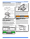
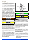
FLOOR BASE AND DUCTWORK INSTALLATION -
DOWNFLOW
Installations on combustible material or directly on any
floors must use a combustible floor base shown in Figure 8,
"Combustible Floor Base Accessory". Follow the instruc-
tions supplied with the combustible floor base accessory.
This combustible floor base can be replaced with a match-
ing cooling coil, properly sealed to prevent leaks. Follow the
instructions supplied with the cooling coil cabinet for install-
ing the cabinet to the duct connector. Plug intake and vent
pipe holes in bottom panel and move grommet to desired
vent side exit.
Downflow Air Conditioning Coil Cabinet
The furnace should be installed with coil cabinet part number specifi-
cally intended for downflow application. If a matching cooling coil is
used, it may be placed directly on the furnace outlet and sealed to pre-
vent leakage. For details of the coil cabinet dimensions and installation
requirements, refer to the installation instructions supplied with the coil
cabinet.
Attach the air conditioning coil cabinet to the duct connector, and then
position the furnace on top of the coil cabinet. The connection to the fur-
nace, air conditioning coil cabinet, duct connector, and supply air duct
must be sealed to prevent air leakage.
COIL INSTALLATION
COIL/FURNACE ASSEMBLY - MC/FC/PC SERIES
COILS
FURNACE ASSEMBLY - MC & FC SERIES COILS
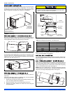
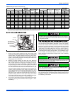
These coils are factory shipped for installation in either upflow or down-
flow applications with no conversion.
Position the coil casing over or under the furnace opening as shown in
Figure 2, "Vertical Applications" after configuring coil flanges as
required see “Coil Flange” section below.
The duct system must be properly sized to obtain the correct airflow
for the furnace size that is being installed.
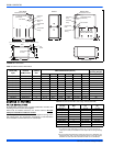
Refer to Table 6, "Ratings & Physical / Electrical Data" or the fur-
nace rating plate for the correct rise range and static pressures.
If the ducts are undersized, the result will be high duct static pres-
sures and/or high temperature rises which can result in a heat
exchanger OVERHEATING CONDITION. This condition can result
in premature heat exchanger failure, which can result in personal
injury, property damage, or death.
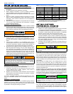
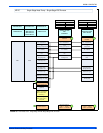
FIGURE 1: Duct Attachment
Factory
installed
For duct attachment,
if needed.
On all installations without a coil, a removable access panel is rec-
ommended in the outlet duct such that smoke or reflected light
would be observable inside the casing to indicate the presence of
leaks in the heat exchanger. This access cover shall be attached in
such a manner as to prevent leaks.
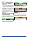
FIGURE 2: Vertical Applications
UPFLOW
DOWNFLOW
Furnace
Furnace