


364861-UIM-B-0708
Johnson Controls Unitary Products 21
SECTION VIII: COMBUSTION AIR AND
VENT SYSTEM
COMBUSTION AIR AND VENT SAFETY
This Category IV, dual certified direct vent furnace is designed for resi-
dential application. It may be installed without modification to the con-
densate system in a basement, garage, equipment room, alcove, attic
or any other indoor location where all required clearance to combusti-
bles and other restrictions are met. The combustion air and the venting
system must be installed in accordance with Section 5.3, Air for Com-
bustion and Ventilation, of the National Fuel Gas Code Z223.1/NFPA 54
(latest edition), or Sections 7.2, 7.3 or 7.4 of CSA B149.1, National Gas
and Propane Codes (latest edition) or applicable provisions of the local
building code and these instructions.
COMBUSTION AIR/VENT PIPE SIZING
The size of pipe required will be determined by the furnace model, the
total length of pipe required and the number of elbows required.
Table 7, "Maximum Equivalent Pipe Length" lists the maximum equiva-
lent length of pipe allowed for each model of furnace. The equivalent
length of elbows is shown in Table 9, "Equivalent Length of Fittings".
The equivalent length of the vent system is the total length of straight
pipe PLUS the equivalent length of all of the elbows.
The following rules must also be followed:
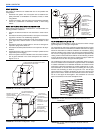
1. Long radius (sweep) elbows are recommended. Standard elbows
may be used, but since they have a longer equivalent length, they
will reduce the total length of pipe that will be allowed. Short radius
(plumbing vent) elbows are not allowed. The standard dimensions
of the acceptable elbows are shown below.
2. The maximum equivalent length listed in Table 7, "Maximum
Equivalent Pipe Length" is for the vent piping and the air intake
piping separately. For example, if the table allows 65 equivalent
feet for a particular model, then the vent can have 65 equivalent
feet of pipe, AND the combustion air intake can have another 65
equivalent feet of pipe.
3. Three vent terminal elbows (two for the vent and one for the com-
bustion air intake) are already accounted for and need not be
included in the equivalent length calculation.
4. All combustion air and vent pipe must conform to American
National Standards Institute (ANSI) and American Society for Test-
ing and Materials (ASTM) standards D1785 (Schedule 40 PVC),
D2665 (PVC-DWV), F891 (PVC-DWV Cellular Core), D2261
(ABS-DWV) or F628 (Schedule 40 ABS). Pipe cement and primer
must conform to ASTM Standard D2546 (PVC) or D2235 (ABS). If
ABS pipe is to be used, any joint where ABS pipe is joined to PVC
pipe must be glued with cement that is approved for use with
BOTH materials. Metallic materials must not
be used for venting or
air intake.
5. If a flexible connector is used in the vent system, it must be made
of a material that is resistant to acidic exposure and to at least
225° F temperature. Flexible connectors are also allowed in the
combustion air pipe.
6. All models are supplied with 2" vent connections. When the pipe
must be increased to 3" diameter, the transition from 2" to 3" must
be done as close to the furnace as possible. For upflow models,
the transition from 2" to 3" should be done immediately above the
furnace. For downflow or horizontal models, the transition from 2"
to 3" pipe should be done immediately after exiting the furnace.
7. In Canada, vents shall be certified to ULC S636, Standard for Type
BH Gas Venting Systems. IPEX System 636 PVC is certified to
this standard.
8. In Canada, the first three feet (900 mm) of the vent must be readily
accessible for inspection.
9. For single pipe systems it is recommended to install the combus-
tion air coupling provided and install approximately 18” of PVC
pipe on the furnace.
10. Minimum vent length for all models is 5 feet.
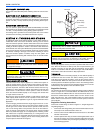
Dimensions are those required in Standard ASTM D-3311.
The “VENT SYSTEM” must be installed as specified in these
instructions for Residential and Non HUD Modular Homes. The
direct vent system is the only configuration that can be installed in a
Non HUD Modular Home.
This furnace may not be common vented with any other appliance,
since it requires separate, properly sized air intake and vent lines.
The furnace shall not be connected to any type of B, BW or L vent
or vent connector, and not connected to any portion of a factory-
built or masonry chimney
The furnace shall not be connected to a chimney flue serving a sep-
arate appliance designed to burn solid fuel.
When combustion air pipe is installed above a suspended ceiling or
when it passes through a warm and humid space, the pipe must be
insulated with 1/2” Armaflex or other heat resistant type insulation if
two feet or more of pipe is exposed.
Vent piping must be insulated if it will be subjected to freezing tem-
peratures such as routing through unheated areas or through an
unused chimney.
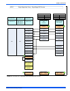
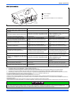
TABLE 7:
Maximum Equivalent Pipe Length
Model Input
BTUH (kW)
Pipe Size
Inches (cm)
Maximum
Equivalent
length feet (m)
40,000 (11.7) 2 (5.1) 65 (19.8)
40,000 (11.7) 3 (7.6) 90 (27.4)
60,000 (17.6) 2 (5.1) 65 (19.8)
60,000 (17.6) 3 (7.6) 90 (27.4)
80,000 (23.4) 2 (5.1) 65 (19.8)
80,000 (23.4) 3 (7.6) 90 (27.4)
100,000 (29.3) 2 (5.1) 30 (9.2)
100,000 (29.3) 3 (7.6) 90 (27.4)
120,000 (35.1) 2 (5.1) 30 (9.2)
120,000 (35.1) 3 (7.6) 90 (27.4)
130,000 (38.1) 3 (7.6) 85 (25.9)
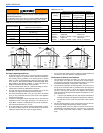
FIGURE 27:
Dimensions
TABLE 8: Elbow
Dimensions
Elbow "A" Dimension
2" Standard 2-5/16"
3" Standard 3-1/16"
2" Sweep 3-1/4"
3" Sweep 4-1/16"
A
A
A
A
STANDARDELBOW
LONG (SWEEP) ELBOW