


NOTES:
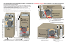
1. Refer to the condensate management and drain hose
plumbing for different configurations in this document. No
hose clamps are needed for the condensate pan hook up.
2. Drip leg in the gas line must be installed.
3. The furnace controls require correct polarity on the power
supply and a proper ground.
4. Y & G must be connected to the control board for cooling
operation.
5. To measure total static pressure add supply duct pressure to
the return duct pressure, add pressure drop across the ‘A’
coil, and add pressure drop across the filter. Ignore negative
signs on the readings.
6. Inlet gas pressure for natural gas should be 7” and that for
propane should be 11” w.c. Nominal manifold gas pressure
is 3.5” for natural gas and 10” w.c. for propane.
7. If thermoplastic evaporator ‘A’ coil drain pans are to be
installed in the up-flow/horizontal configuration, then extra 2”
minimum spacing may be needed to ensure against drain
pan distortion.
8. External filters required on all configurations.
9. Electrical entry is available on both sides of the casing.
10. All 33”, 95% furnaces are approved for single-pipe and 2-
pipe systems. For single pipe systems it is recommended to
install the combustion air coupling provided and install
approximately 18” of PVC pipe on the furnace.
11. Do not install an external condensate trap on these fur-
naces, as it will prevent the unit from operating correctly.
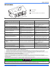
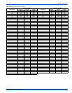
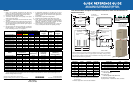
Models
Airflow CFM (Bottom Return without Filters)
Minimum Wire
Size awg @ 75'
One-Way
Total Unit
Amps
Maximum
Over Current
Protection
0.5" ESP (Nominal)
Low Med-Lo Med-Hi High
(T,G)G9S040A08MP11 581 653 818 950 14 8.0 15
(T,G)G9S060A10MP11
769 917 1038 1103 14 10.0 15
(T,G)G9S060B12MP11
713 872 1082 1243 14 10.0 15
(T,G)G9S080B12MP11 854 1008 1179 1370 14 10.0 15
(T,G)G9S080C16MP11
838 1250 1465 1671 14 11.5 15
(T,G)G9S080C22MP11
1285 1586 1937 2162 12 17.0 20
(T,G)G9S100C16MP11 819 1224 1477 1706 14 11.5 15
(T,G)G9S100C20MP11
1183 1430 1712 1934 12 17.0 20
(T,G)G9S120D16MP11
876 1254 1495 1805 14 11.5 15
(T,G)G9S120D20MP11 1190 1430 1739 1977 12 17.0 20
(T,G)G9S130D20MP11
1198 1459 1786 2047 12 17.0 20
Models
Maximum
Vent Equivalent
1
Factory Heating
Speed Setting
2
Temperature
Rise Range
Time For 1 ft
3
Natural Gas
(1030 Btu/Ft
3
)
Seconds On (Rate)
2" 3"
(T,G)G9S040A08MP11 65’ 90’ Med-Hi 30°F-60°F 93
(T,G)G9S060A10MP11 65’ 90’ High 30°F-60°F 62
(T,G)G9S060B12MP11 65’ 90’ Med-Hi 30°F-60°F 62
(T,G)G9S080B12MP11 65’ 90’ High 35°F-65°F 46
(T,G)G9S080C16MP11 65’ 90’ High 35°F-65°F 46
(T,G)G9S080C22MP11 65’ 90’ Med-Hi 35°F-65°F 46
(T,G)G9S100C16MP11 30’ 90’ High 35°F-65°F 37
(T,G)G9S100C20MP11 30’ 90’ Med-Hi 35°F-65°F 37
(T,G)G9S120D16MP11 30’ 90’ High 40°F-70°F 30
(T,G)G9S120D20MP11 30’ 90’ Med-Hi 35°F-65°F 30
(T,G)G9S130D20MP11 N/A 85’ High 45°F-75°F 28
1. For venting purposes, one 90° sweep elbow is equal to 5 Ft. of venting length, one 90° standard elbow is equal to 10 equiva-
lent feet of vent length. Vent termination elbows are not included in these calculations, minimum required vent length is 15 ft.
2. Must be changed if not in rise range.
This document does not replace the installation instructions, which must be referred to for
detailed information.
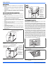
CLEARANCES
* 24" clearance in front and 18" on side recommended for
service access.
All furnaces approved for alcove and attic installation.
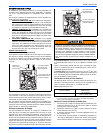
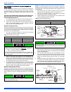
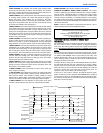
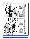
DIMENSIONS
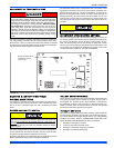
LED INDICATOR
Slow Green Flash
• Normal operation
Slow Amber Flash
• Normal operation with call for heat
Any Red Flash = Fault condition
Any Rapid 4 Flash = Potential fault codes / conditions
SUPPLY END
RETURN END
LEFT SIDE
Combustion Air Inlet
Condensate Drain
(Downflow)
Vent Connection
Outlet
Thermostat
Wiring
29.5”
28.5”
RIGHT SIDE
Condensate Drain
(Downflow)
14”
1”
1.5”
23”
Combustion Air Inlet
Gas Pipe
Entry
Electrical
Entry
Condensate
Drain
Optional Return Air
Cutout (Either side)
FRONT
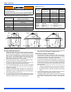
A
33”
Clips can be flipped
into the up position
for coil cabinet or
plenum attachment
A-COIL
Follow all national, local codes and standards in addition to this document. The installation
must comply with regulations of the serving gas supplier, local building, heating, plumbing,
and other codes. In absence of local codes, the installation must comply with the national
codesand allauthorities havingjurisdiction.
B
24.25”
.56”
.56”
20”
3”
23.8”
.56”
Combustion
Air Inlet
2” Diameter
Vent Connection
Outlet
B
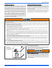
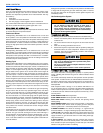
DURING INSTALLATION,
DOORS MUST REMAIN ON
FURNACE WHEN MOVING
OR LIFING.
Vent Connection
Outlet
Application Upflow Downflow Horizontal
Top 1" 0" 0"
Vent 0" 0" 0"
Rear 0" 0" 0"
Side 0" 0" 1"
Front* 0" 0" 0"
Floor Combustible
Combustible
1
1. For combustible floors only when used with special
sub-base.
Combustible
Closet Yes Yes Yes
Line Contact No No Yes
Cabinet Size A (in) B (in)
All 'A' Cabinet Furnaces 14-1/2" 13-3/8"
All 'B' Cabinet Furnaces 17-1/2" 16-3/8"
All 'C' Cabinet Furnaces 21" 19-7/8"
All 'D' Cabinet Furnaces 24-1/2" 23-3/8"
QUICK REFERENCE GUIDE
95.5% SINGLE STAGE MULTI-POSITION
RESIDENTAL GAS FURNACES (33” TALL)
Subject to change without notice. Printed in U.S.A. 401260-URG-C-0808
Copyright © 2008 by Johnson Controls, Inc. All rights reserved. Supersedes: 401260-URG-B-0708
Johnson Controls Unitary Products
5005 York Drive
Norman, OK 73069
*401260*