


364861-UIM-B-0708
16 Johnson Controls Unitary Products
SECTION VII: CONDENSATE PIPING AND
FURNACE VENTING CONFIGURATION
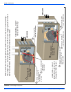
CONDENSATE DRAIN LOCATION
As shipped from the factory:
• For all 040, 060, & 080K input furnaces the main drain is plumbed
through the casing right-side opening when viewed from the front
of the furnace.
• For all 100, 120, & 130K input furnaces the main drain is plumbed
through the casing left-side opening when viewed from the front
of the furnace.
NOTE: On 130K BTU models, there is no provision for the vent to
exit the top of the cabinet, the vent must always exit one of the
sides.
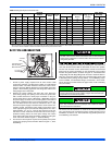
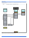
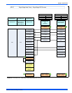
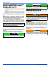
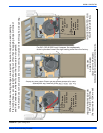
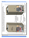
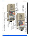
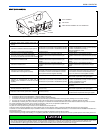
NOTE: The Figures 23 - 26 show the condensate drain arrange-
ment for the various possible furnace and vent blower positions.
The condensate hoses must slope downwards at all points.
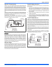
The condensate water will flow to the drain better id a tee with a short,
open end, length of pipe is installed in the drain line. The top of the pipe
should terminate at least to the middle of the condensate pan which is
located inside the furnace.
When drain hose routing changes are required (shown in Figures 23-
26), be sure to cap all un-used openings.
If rerouting hoses - excess length should be cut off so that no sagging
loops will collect and hold condensate - which will cause the furnace to
not operate.
No hose clamps are needed for connecting to the condensate pan.
CONDENSATE DRAIN TERMINATION
A condensate sump pump MUST be used if required by local codes, or
if no indoor floor drain is available. The condensate sump pump must
be approved for use with acidic condensate.
CONDENSATE DRAIN TRAP AND DRAIN FREEZE
PROTECTION
Special precautions MUST be made if installing furnace in an area
which may drop below freezing. This can cause improper operation or
damage to the equipment. If the furnace is installed in an area that has
the potential of freezing, the drain line must be protected. Use a 3 to 6
watt per foot at 115 vac, 40º F (4.4° C) self-regulating, shielded and
waterproof heat tape. Wrap the drain line outside of the furnace with the
heat tape and secure with ties. Follow the heat tape manufacturer's rec-
ommendations.
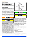
The furnace condensate pan is self priming and con-
tains an internal trap to prevent flue gas leaking. Do
not install an external condensate trap.
The condensate drain from the furnace may be connected in com-
mon with the drain from an air conditioning coil if allowed by local
code.
Condensate must be disposed of properly. Follow local plumbing or
wastewater codes. The drain line must maintain a 1/4" per foot
(0.635 cm per meter) downward slope to the drain.
DO NOT terminate condensate drain in a chimney, or where the
drain line may freeze. The line must terminate at an inside drain to
prevent freezing of the condensate and possible property damage.
DO NOT trap the drain line at any other location than at the conden-
sate drain trap supplied with the furnace.
Use only Propylene Glycol (RV anti-freeze) to winterize the furnace.
Refer to the manufacturer’s specification to ensure that it is compat-
ible with plastics and other components of the furnace. DO NOT
use Ethylene Glycol anti-freeze in the furnace.