


47
NPSH
The minimum operating values that can be reached at the
pump suction end are limited by the onset of cavitation.
Cavitation is the formation of vapor-filled cavities within
liquids where the pressure is locally reduced to a critical
value, or where the local pressure is equal to, or just below
the vapor pressure of the liquid.
The vapor-filled cavities flow with the current and when
they reach a higher pressure ares the vapor contained in
the cavities condenses. The cavities collide, generating
pressure waves that are transmitted to the walls. These,
being subjected to stress cycles, gradually become de-
formed and yield due to fatigue. This phenomenon, char-
acterized by a metallic noise produced by the hammering
on the pipe walls, is called incipient cavitation.
The damage caused by cavitation may be magnified by
electrochemical corrosion and a local rise in temperature
due to the plastic deformation of the walls. The materials
that offer the highest resistance to heat and corrosion are
alloy steels, especially austenitic steel. The conditions that
trigger cavitation may be assessed by calculating the total
net suction head, referred to in technical literature with
the acronym NPSH (Net Positive Suction Head).
The NPSH represents the total energy (expressed in feet) of
the liquid measured at suction under conditions of incipi-
ent cavitation, excluding the vapor pressure (expressed in
feet) that the liquid has at the pump inlet.
To find the static height (hz) at which to install the ma-
chine under safe conditions, the following formula must
be verified:
h
p
+ h
z
≥ (NPSHr + 2 feet) + h
f
+ h
pv
where:
h
p
is the absolute pressure applied to the free liquid sur-
face in the suction tank, expressed in feet of liquid; hp
is the quotient between the barometric pressure and
the specific weight of the liquid.
h
z
is the suction lift between the pump axis and the free
liquid surface in the suction tank, expressed in feet;
hz is negative when the liquid level is lower than the
pump axis.
h
f
is the flow resistance in the suction line and its acces-
sories, such as: fittings, foot valve, gate valve, elbows,
etc.
h
pv
is the vapor pressure of the liquid at the operating
temperature, expressed in feet of the liquid. hpv is
the quotient between the Pv vapor pressure and the
liquid‘s specific weight.
0.5 is the safety factor.
The maximum possible suction head for installation de-
pends on the value of the atmospheric pressure (i.e. the
elevation above sea level at which the pump is installed)
and the temperature of the liquid.
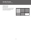
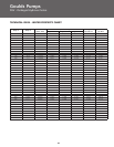
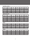
To help the user, with reference to water temperature
(40ºF) and to the elevation above sea level, the following
tables show the drop in hydraulic pressure head in relation
to the elevation above sea level, and the suction loss in
relation to temperature.
Water
68 104 140 176 194 230 248
Temperature (°C)
Suction
-.7 2.3 6.6 16.4 24.3 50.5 70.5
Loss (ft)
Elevation Above
1600 3300 4900 6500 8200 9800
Sea Level (ft)
Suction
1.8 3.6 5.4 7.2 9.0 10.8
Loss (ft)
To reduce it to a minimum, especially in cases of high suc-
tion head (over 13 – 16 feet) or within the operating limits
with high flow rates, we recommend using a suction line
having a larger diameter than that of the pump’s suction
port. It is always a good idea to position the pump as close
as possible to the liquid to be pumped.