


65178X-XXX-B (en) Page 7 of 8
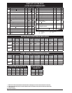
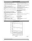
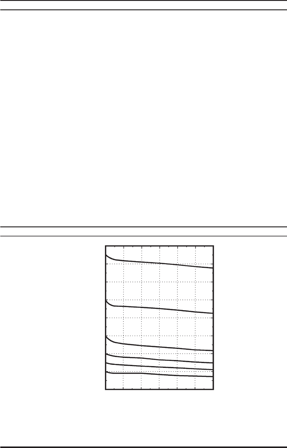
PERFORMANCE DATA
SERVICE NOTE: “DRI-SLIDE”, FXR is a commercially available anti-rust lubricant (contains 9% Molybdenum Disul de) or Molybdenum Disul-
de powder with or without light oil carrier.
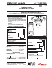
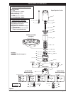
Also refer to parts list and views on pages 4 and 5.
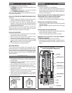
1. Place the (40) stem in a vise. Use the ats provided.
2. Position the (19) “O” ring in the groove.
3. Place the (17) white diaphragm onto the (40) stem center.
4. Place the (16) cream colored diaphragm onto the (40)
stem.
5. Place the (13) piston on the assembly.
6. Install the (11) lockwasher and the (10) screw.
NOTE: Make certain the diaphragm holes are in alignment
before tightening the (10) screw. Torque to 65 - 75 in. lbs (7.3
- 8.5 Nm).
SERVICE HINT: Use the (14) screw to help align the diaphragm
holes.
7. Remove the diaphragm / piston / stem assembly from the
vise.
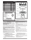
UPPER REGULATOR BODY SECTION REASSEMBLY
NOTE: (from page 4 parts list) If the (1) housing has been
removed and disassembled, the (7) plate should be re-
placed.
8. Place the (48) base in a vise, using the ats.
9. Place the (15) plate over the diaphragm / piston / stem
assembly.
10. Apply Loctite 271 to the (14) screw.
11. Install the (14) screws.
NOTE: Tighten the short bolts alternately and evenly.
Tighten snug.
Tighten to 20 - 25 ft lbs (27.1 - 33.9 Nm).
Tighten to 50 - 55 ft lbs (67.8 - 74.6 Nm).
12. Place the (12) plate (ball side down) into the hex of the (10)
screw.
13. Place the (9) spring on top of the (12) plate.
14. Place the (22) spring stop over the (9) spring.
15. Place the bonnet / adjusting screw assembly over the
spring.
16. Retain the bonnet with the (3) lockwashers and (2) bolts.
Tighten alternately until snug, then torque to 20 - 25 ft
lbs (27.1 - 33.9 Nm).
17. Place the (18) “O” ring into the groove.
18. Apply “DRI-SLIDE” to the surface of the (13) piston.
19. Install the diaphragm / piston / stem assembly and align
with the base hole pattern.
20. Turn the regulator over and vise on ats.
REGULATOR VALVE SECTION REASSEMBLY
DOWNSTREAM MODELS
Install (41) “O” ring.
Install (42) seat.
Install the (45) ow tube.
Install the (43) ball.
Install the (44) spring with the narrow end against the
ball.
Install the (47) valve plug and “O” ring assembly.
Tighten until snug.
BACK PRESSURE MODELS
Install (41) “O” ring.
Install (42) seat.
Install the (45) ow tube.
Install the (47) valve plug and “O” ring assembly.
Tighten until snug.
REGULATOR REASSEMBLY
G.P.M. 1 2 3 4 5 6
(l.p.m.) (3.8) (7.6) (11.4) (15.1) (18.9) (22.7)
3200
(221)
2800
(193)
2400
(166)
2000
(138)
1600
(110)
1200
(83)
800
(55)
400
(28)
P.S.I.
(bar)
R
E
G
U
L
A
T
E
D
P
R
E
S
S
U
R
E
Fluid Flow
Figure 9