


Page 6 of 8 65178X-XXX-B (en)
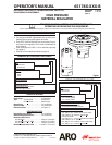
(refer to pages 4 and 5)
FOR “WARNINGS”, REFER TO “OPERATING AND SAFETY
PRECAUTIONS” ON PAGE 2 FOR DETAILS.
BEFORE SERVICING, READ “WARNING: DISASSEMBLY
HAZARD.” FOUND ON PAGE 2.
TOOLS REQUIRED: Small bench vise, 3/8” Allen wrench
(Y106-109 is included), 5/32” Allen wrench, a 9/16” Allen
wrench for -CXX-B models, torque wrench and Loctite 242.
NOTE: It is not always necessary to remove the regulator from
the uid line to service or inspect only the valve section.
BEFORE DOING ANY IN-LINE SERVICE, ALL FLUID PRES-
SURE MUST BE RELIEVED. HEED ALL WARNINGS FOUND
ON PAGE 2.
ALLEN WRENCH NOTE: The Y106-109 (3/8”) Allen wrench
is included and can be used for several functions including:
Regulator adjustment (spring type models), removal and as-
sembly of the long bonnet bolts and the short plate bolts.
VALVE SEAT NOTE: Before deciding to order a general repair
kit to service the whole regulator, check the easiest things
rst. Remove and inspect the valve seat for dirt, foreign mat-
ter, damage or wear (steps 1 - 3).
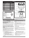
DOWNSTREAM STYLE MODELS
1. Remove the (46 / 47) base plug / “O” ring assembly, which
will allow removal of the (44) spring, (43) ball, (45) flow
tube, (42) seat and (41) “O” ring.
BACK PRESSURE STYLE MODELS
2. Remove the (46 / 47) base plug / “O” ring assembly, which
will allow the removal of the (45) ow tube, (42) seat and
(41) “O” ring.
3. Inspect the (42) seat for dirt, damage or wear.
READ “WARNING: BONNET REMOVAL HAZARD” FOUND
ON PAGE 2.
4. Remove the four (2) long bolts to allow removal of the
bonnet / adjusting screw assembly.
NOTE: The (6) adjusting screw, (5) thrust bearing and (4)
washer are retained by (7) plate, which is pressed into place.
It should not be necessary to disassemble these parts during
normal service.
5. Remove the (9) regulator spring and (12) small plate.
6. Remove the (14) bolts.
7. Remove the (15) plate.
8. Remove the stem / diaphragm and piston assembly.
9. Place the stem in a vise, locate and secure on the stem
ats provided.
10. Using a 5/32” hex Allen wrench, remove the (10) screw.
11. Remove the (11) lockwasher, (13) piston, two (16, 17)
diaphragms and (18 and 19) “O” rings from the (40) valve
stem.
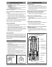
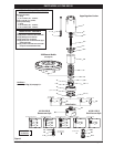
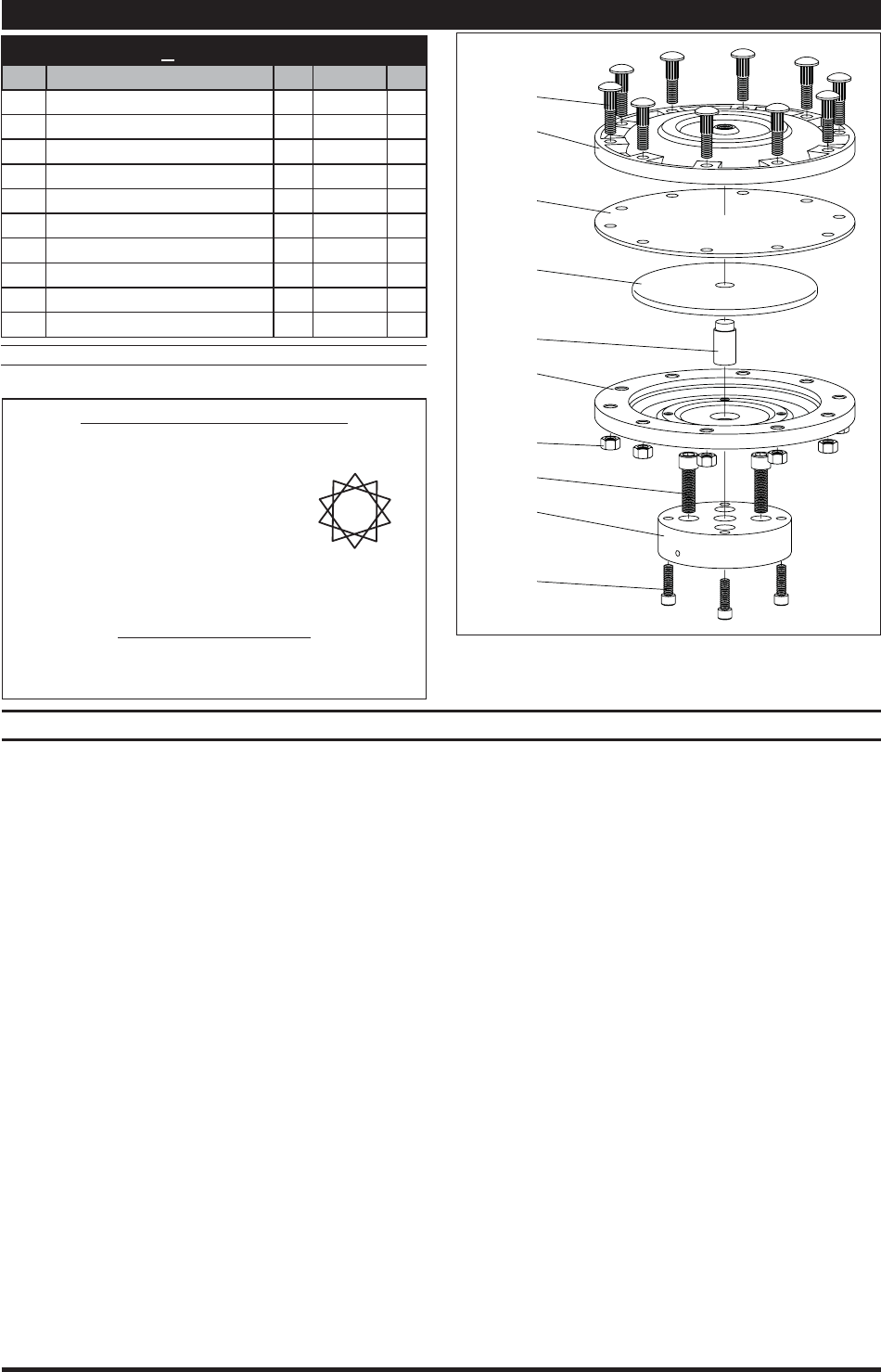
REMOTE MODELS (Refer to gure 8)
1. Remove four (34) screws from (30) air cap and separate
the diaphragm assembly from the (33) adapter.
2. Disassemble the diaphragm assembly by removing the
ten (31) nuts.
3. Separate the two halves to allow inspection of the (27)
diaphragm and replace, if necessary.
4. Reassemble in reverse order.
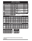
651780-XXR-B REMOTE MODELS
Item Description
(size)
(Qty) Part No. [Mtl]
25 Ribbed Bolt
(3/8” - 16 x 1-1/2”)
(10) 93750-1 [C]
26 Air Cap (1) 93753-1 [A]
27 Diaphragm (1) 93754-1 [N]
28 Plate (1) 94573 [C]
29 Piston (1) 93751-1 [C]
30 Air Cap (1) 93753-2 [A]
31 Nut
(3/8” - 16)
(10) Y12-6-C [C]
32 Cap Screw
(7/16” - 20 x 2”)
(4) Y157-76 [C]
33 Adapter (1) 93752-1 [A]
34
Cap Screw
(5/16” - 18 x 1”)
(4) Y99-52 [C]
MATERIAL CODE
[A] = Aluminum [C] = Carbon Steel [N] = Neoprene
PARTS LIST
ASSEMBLY TORQUE REQUIREMENTS
NOTE: DO NOT OVERTIGHTEN FASTENERS.
(31) Torque in sequence.
1.) Snug.
2.) 20 ft lbs (27.1 Nm).
(32) Torque alternately.
1.) Snug.
2.) 20 - 25 ft lbs (27.1 - 33.9 Nm).
(34) Torque alternately.
1.) Snug.
2.) 10 ft lbs (13.6 Nm).
LUBRICATION / SEALANTS
Apply Loctite 242® to threads.
Secure (29) piston to (28) plate with Loctite 680™ Retaining
Compound. Apply “DRI-SLIDE” upon reassembly.
Figure 7
27
28
29
30
31
25
26
32
33
34
Figure 8
"Smart parts", keep these items on hand in addition to the ser-
vice kits for fast repair and reduction of down time.
REGULATOR DISASSEMBLY
1
2
3
4
5
6
7
8
9
10