


65178X-XXX-B (en) Page 5 of 8
45
46
47
45
46
47
40
17
(white)
41
42
41
42
41
42
43
44
41
42
43
44
41
42
43
44
40 40
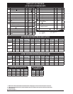
(651780-AXX-B) (0.1875”) (651780-CXX-B) (0.500”) (651781-BXX-B) (651781-CXX-B)
(65178X-AXX-B)
(65178X-BXX-B)
(65178X-CXX-B)
(651780-AXX-B)
(651780-BXX-B)
(651780-CXX-B)
(651781-BXX-B) (651781-CXX-B)
48
18
40
(651780-BXX-B) (0.250”)
19
(cream colored)
16
15
13
11
14
10
12
9
22
8
7
6
5
4
1
3
2
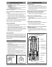
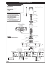
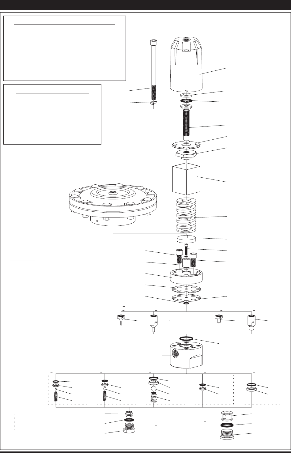
PARTS VIEW / 65178X-XXX-B
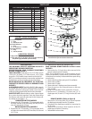
ASSEMBLY TORQUE REQUIREMENTS
NOTE: DO NOT OVERTIGHTEN FASTENERS.
(2) Torque alternately.
1.) Snug.
2.) 20 - 25 ft lbs. (27.1 - 33.9 Nm).
(10) 65 - 75 in. lbs. (7.3 - 8.5 Nm).
(14) Torque alternately.
1.) Snug.
2.) 20 - 25 ft lbs. (27.1 - 33.9 Nm).
3.) 50 - 55 ft lbs. (67.8 - 74.6 Nm).
Figure 6
LUBRICATION / SEALANTS
Apply “DRI-SLIDE” upon assembly.
Apply Loctite® nickel anti-seize to threads.
Apply 40036 grease to threads.
Apply Loctite 271™ to threads.
Apply Perma-Lok® LH150 anaerobic pipe
sealant to threads.
Apply Loctite nickel anti-seize to threads
(except on models 65178X-X1X-B).
Upper Regulator Section
Valve Section
-XXR Remote Models
(see page 6)
651780-XXX-B
Downstream Style
651781-XXX-B
Back Pressure Style
Not Shown
Item 52 Pipe Plug (2) (see page 4)
Parts available
in valve kit.