


30
icos - Installation & Servicing
INSTALLATION
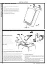
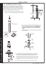
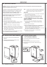
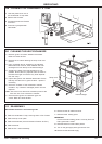
B. GAS INSTALLATION
1. The whole of the gas installation, including the meter,
should be inspected and tested for soundness and purged
in accordance with the recommendations of BS. 6891.
In IE refer to I.S. 813:2002.
2. Purge air from the gas installation by the approved methods
only.
WARNING
. Whilst effecting the required gas soundness test and purging air from the gas
installation, open all windows and doors, extinguish naked lights and DO NOT SMOKE.
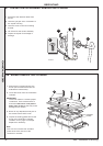
A. ELECTRICAL INSTALLATION
1. Checks to ensure electrical safety should be carried out by
a competent person.
2. ALWAYS carry out the preliminary electrical system checks,
i.e. earth continuity, polarity, resistance to earth and short
circuit, using a suitable test meter.
40
COMMISSIONING AND TESTING
39
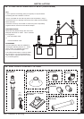
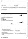
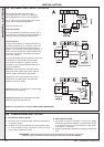
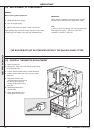
EXTERNAL ELECTRICAL CONTROLS
Wiring external to the boiler MUST be in
accordance with the current I.E.E. (BS.7671)
Wiring Regulations and any local regulations.
For IE reference should be made to the current
ETCI rules for electrical installations.
The fuse should be 3A.
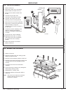
Room Thermostat
If the thermostat has a neutral connection use it.
(It provides for more energy efficient operation by
reducing switching temperature differentials.)
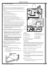
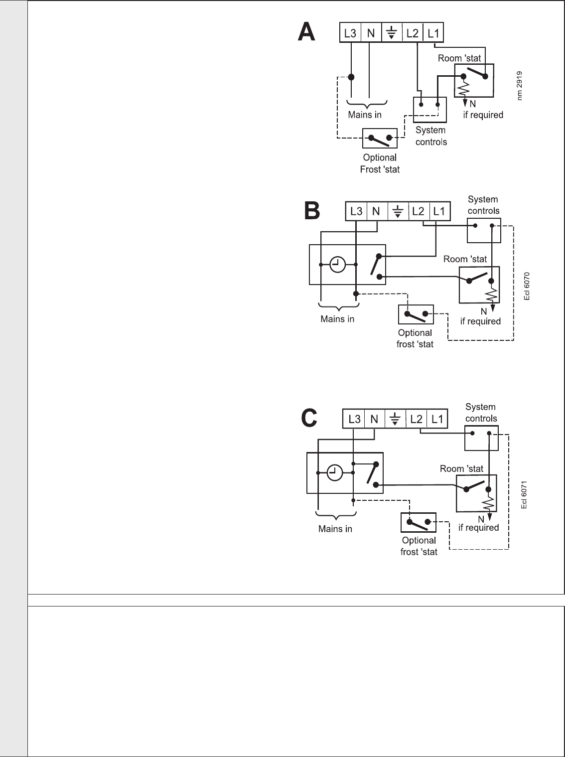
Frost Protection
If parts of the pipework run outside the house or if
the boiler will be left off for more than a day or so
then a frost thermostat should be wired into the
system. This is usually done at the programmer, in
which case the programmer selector switches are
set to OFF and all other controls MUST be left in
the running position.
The frost thermostat should be sited in a cold place
but where it can sense heat from the system.
If the boiler is installed in a garage it may be
necessary to fit a pipe thermostat, preferably on
the return pipework.
Important. Ensure that the frost thermostat is
wired so that the system pump and/or external
diverter valve is energised, as appropriate.
Designation of the terminals will vary but the
programmer and thermostat manufacturers'
leaflets will give full details.
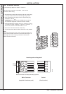
Diagram A shows an application to boilers fitted
with a room thermostat only.
Diagrams B and C show applications to boilers
fitted with alternative time controls.
Earths are not shown for clarity but MUST NEVER BE OMITTED.
INSTALLATION