


16
icos - Installation & Servicing
INSTALLATION
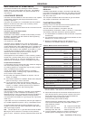
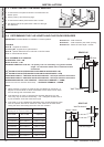
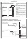
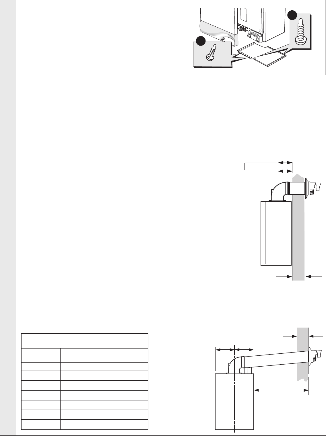
Wall Thickness X
160 mm
160 + S = 193mm
nm8943
13
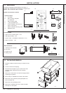
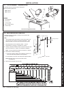
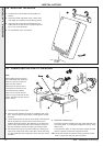
FRONT AND BOTTOM PANEL REMOVAL
IMPORTANT. The boiler MUST be installed in a vertical position.
Dimension X - Wall thickness.
Dimension L - Wall thickness plus boiler spacing.
Dimension S - Stand-off frame depth = 33mm.
1. To remove the front panel remove the 2 screws from the
bottom panel.
2. Lift the panel up and off the top pegs.
3. To remove the bottom panel remove the 2 screws.
4. Pull the RH side of the panel down. Slide it to the right
and withdraw.
14
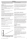
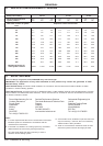
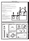
DETERMINING THE FLUE LENGTH AND FLUE PACKS REQUIRED
FLUE KITS
Pack B - supplied as standard.
Finishing Kit - supplied as an optional extra.
Pack D - optional extension kit for side flue or rear flue outlet.
Refer to 'Flue Extension Ducts'
Note. MAXIMUM FLUE LENGTHS:
HORIZONTAL FLUE - 6M
ROOF FLUE KIT - 7.5M
POWERED VERTICAL FLUE KIT - 5m primary and 17m secondary is a typical maximum
length. For alternative details refer to Powered Vertical
Instructions.
90
O
ELBOW KIT 60/100 (EQUIVALENT FLUE LENGTH RESISTANCE = 1M)
45
O
ELBOW KIT 60/100 (EQUIVALENT FLUE LENGTH RESISTANCE = 0.6M)
60/60 TWIN FLUE KIT - 18M TOTAL AIR PLUS FLUE DUCT - Ref Graph within Kit Instructions
80/80 TWIN FLUE KIT - 60M TOTAL AIR PLUS FLUE DUCT - Ref Graph within Kit Instructions
MINIMUM HORIZONTAL FLUE LENGTHS - TELESCOPIC TERMINAL = 370MM
(Centre Line of turret to outside of wall terminal) - ONE PIECE TERMINAL = 285MM
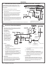
Notes.
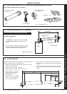
1. When extension ‘D’ packs are used the flue duct MUST be inclined at 1.5
degrees to the horizontal to allow condensate to drain back into the boiler
and out through the condensate drain.
2. If the telescopic ‘B’ pack or horizontal flue terminal (600 long) only are
used, they may be mounted horizontally. The 1.5 degrees is taken care of
by the inclination of the flue within the air pipe
3. If the boiler is to be installed with downward piping routed behind the boiler
then the optional stand-off kit should be used. Care must be taken when
cutting the ducts and marking the wall to suit this condition.
3
1
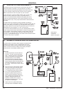
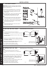
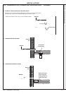
REAR FLUE
SIDE FLUE
195mm
195mm
Wall Thickness X
Side flue length L
Total Flue length dimension Flue
(measuring from CL of turret to outside wall)
Rear flue Side flue Extra packs
dim. X+160 dim. L+195 required
Up to 595 mm Up to 595 mm none
Up to 1545 mm Up to 1545 mm Pack D - 1 off
Up to 2495 mm Up to 2495 mm Pack D - 2 off
Up to 3445 mm Up to 3445 mm Pack D - 3 off
Up to 4395 mm Up to 4395 mm Pack D - 4 off
Up to 5345 mm Up to 5345 mm Pack D - 5 off
Up to 6000 mm Up to 6000 mm Pack D - 6 off
INSTALLATION