


8 41973-01 03/08/2006
ENGLISH
aSSembly ContInued
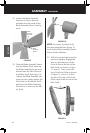
FIGURE 11
1
2
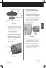
FIGURE 10
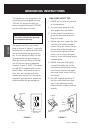
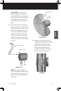
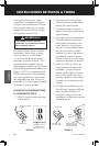
note: For clarity, the Back Grille
has been removed from Figure 10
to show the Blade Assembly Sleeve/
Motor Shaft installation.
23. Slide the Blade Assembly Sleeve
over the Motor Shaft, ensuring
the Blade Assembly Screw is po-
sitioned over the Flat Portion of
the Motor Shaft. See Figure 10.
Tighten the Blade Assembly Set-
screw so that it seats against the
Flat Portion of the Motor Shaft.
gently pull the Blade Assembly
to ensure it is secure on the Mo-
tor Shaft.
24. With the Hunter logo facing for
-
ward and upright, engage the
tabs on the lower part of the
Front Grille into the rim of the
Back Grille, as shown in Figure
11, arrow 1. Then, move the
top of the Front Grille as shown
in Figure 11, arrow 2, so that
the tab at the top of the Front
Grille snaps under the rim of the
Back Grille.
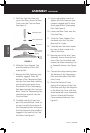
Setscrew
Hole
Blade
Assembly
Sleeve
Blade
Assembly
Setscrew
FIGURE 9
22. Loosen the Blade Assembly
Setscrew so that it does not
protrude into the inside of the
Blade Assembly Sleeve. See Fig-
ure 9.