


6 41973-01 03/08/2006
ENGLISH
aSSembly ContInued
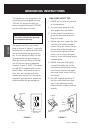
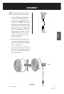
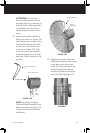
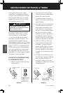
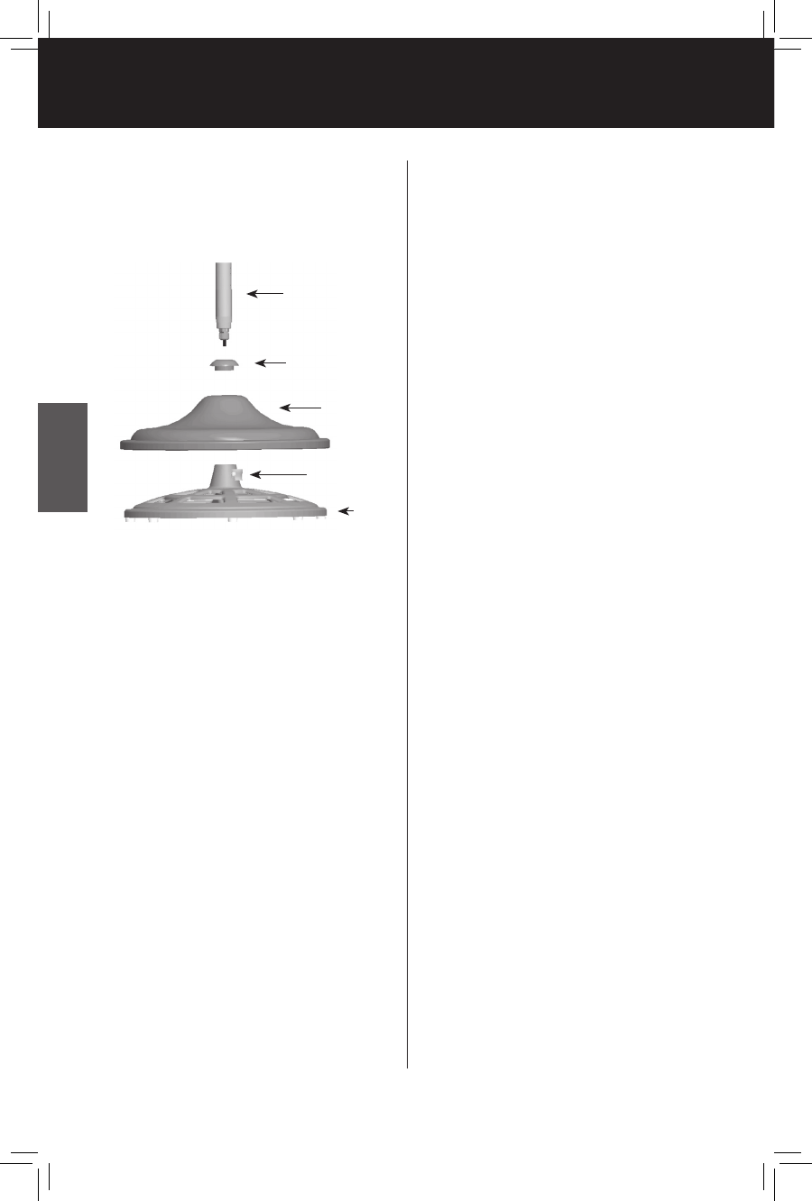
FIGURE 5
Telescoping Pole
Cover Support Cap
Base Cover
Pole Setscrew
(pre-installed,
tagged)
Cast
Iron
Base
5. With the Cast Iron Base rest-
ing on the floor, place the Base
Cover over the Cast Iron Base.
See Figure 5.
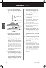
6. Slide the Cover Support Cap
over the bottom of the Tele-
scoping Pole.
7. Remove the Pole Setscrew (pre-
installed, tagged). Place the
bottom of the Telescoping Pole
into the Cast Iron Base, making
sure the plug connector from
the bottom of the Telescoping
Pole goes through the Cast Iron
Base. Twist the Telescoping Pole
clockwise to secure it into the
Cast Iron Base.
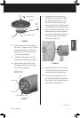
8. Carefully raise the Cover Sup
-
port Cap and the Base Cover so
as not to scratch the surface of
the Telescoping Pole, and locate
the Pole Setscrew (pre-installed,
tagged) in the neck of the Cast
Iron Base. See Figure 5.
9. Use an adjustable wrench to
tighten the Pole Setscrew (pre-
inserted, tagged) until it stops
firmly against the Telescoping
Pole. See Figure 5.
10. Lower the Base Cover over the
Cast Iron Base.
11. Twist the Cover Support Cap
clockwise into the Cast Iron
Base until it is tight.
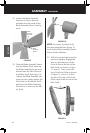
12. Carefully lean the entire assem
-
bly over so that it rests on its
side on the floor.
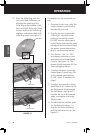
13. Remove one of the four Cover
Assembly Screws from the bot-
tom of the Cast Iron Base and
loosen the three remaining Cov-
er Assembly Screws. See Figure
6.
14. Connect the plugs coming from
the bottom of the Telescoping
Pole and the inside of the Elec-
trical Cover.
15. Place the Electrical Cover
against the bottom of the Cast
Iron Base and align the Keyslots
in the Electrical Cover with the
three loosened Cover Assembly
Screws. Rotate the Electrical
Cover counterclockwise. See
Figure 6.