


41973-01 03/08/2006 7
ENGLISH
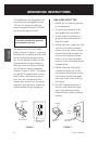
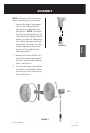
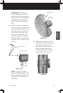
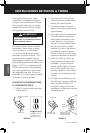
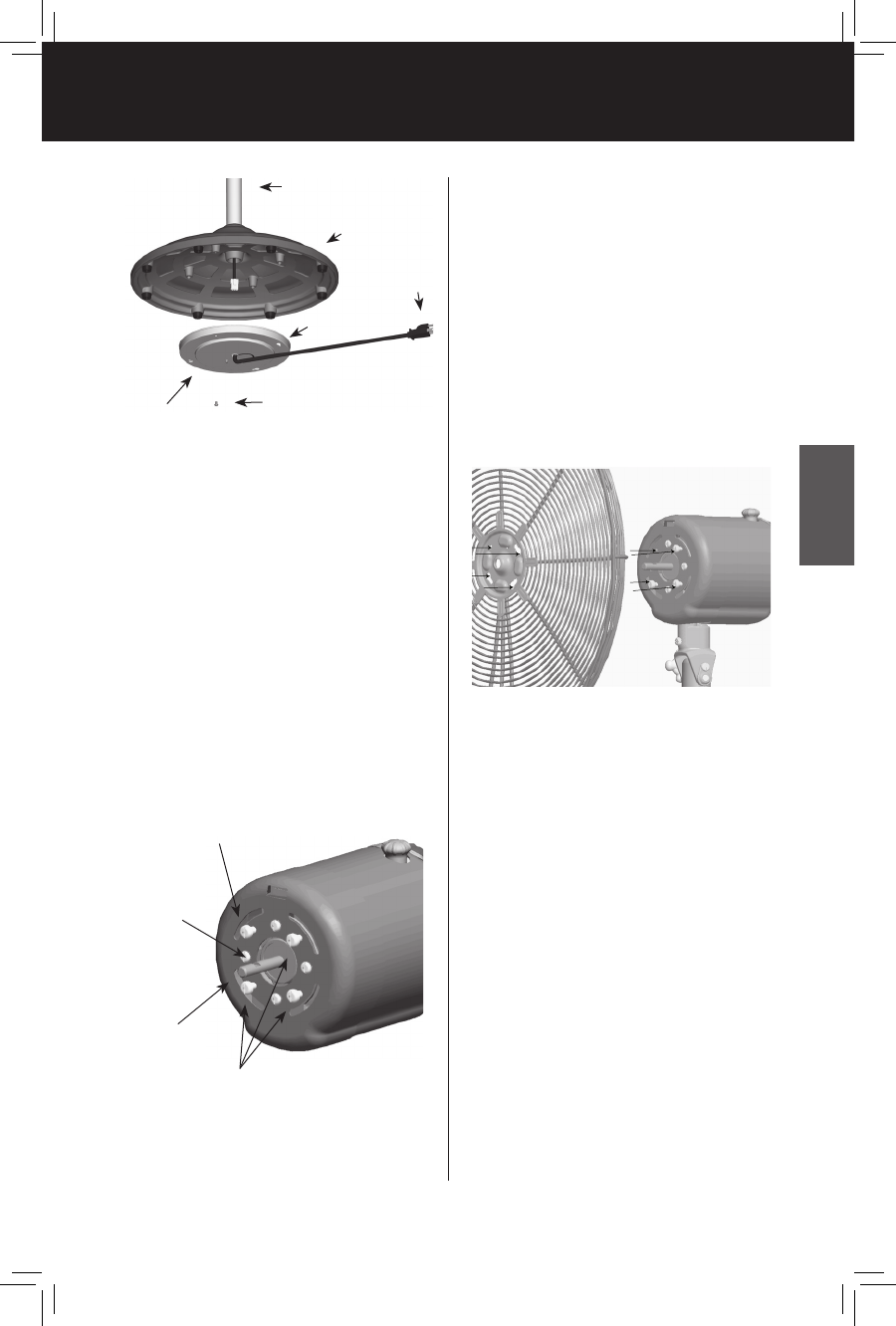
Electrical
Cover
Cover Assembly Screw
Telescoping Pole
Base
Wall
Plug
FIGURE 6
Keyslots
continued
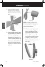
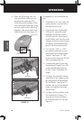
FIGURE 8
Upper Left Grille
Mounting Screw
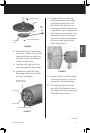
FIGURE 7
Flat Portion
Motor Shaft
Grille Mounting Screws
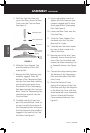
16. Install the fourth Cover Assem-
bly Screw. Tighten all four Cover
Assembly Screws to attach the
Electrical Cover to the bottom
of the Cast Iron Base.
17. Hold the wall plug out of the
way and stand the fan upright.
18. Remove the upper left Grille
Mounting Screw from the Mo-
tor Face. See Figure 7.
19. Loosen the three remaining
Grille Mounting Screws. Align
the three keyhole slots in the
Back Grille with the three re-
maining Grille Mounting Screws
in the Motor Face, and place the
Back Grille onto the Motor Face,
ensuring that the Grille Mount-
ing Screw washers are between
the screw head and the Back
Grille. See Figure 8.
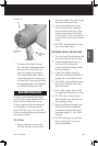
20. Rotate the Back Grille clockwise
to situate the screws in the nar-
row ends of the keyhole slots.
21. Reinstall and tighten the Up
-
per Left Grille Mounting Screw
and tighten the three remaining
Grille Mounting Screws.