


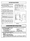
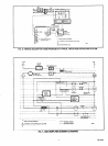
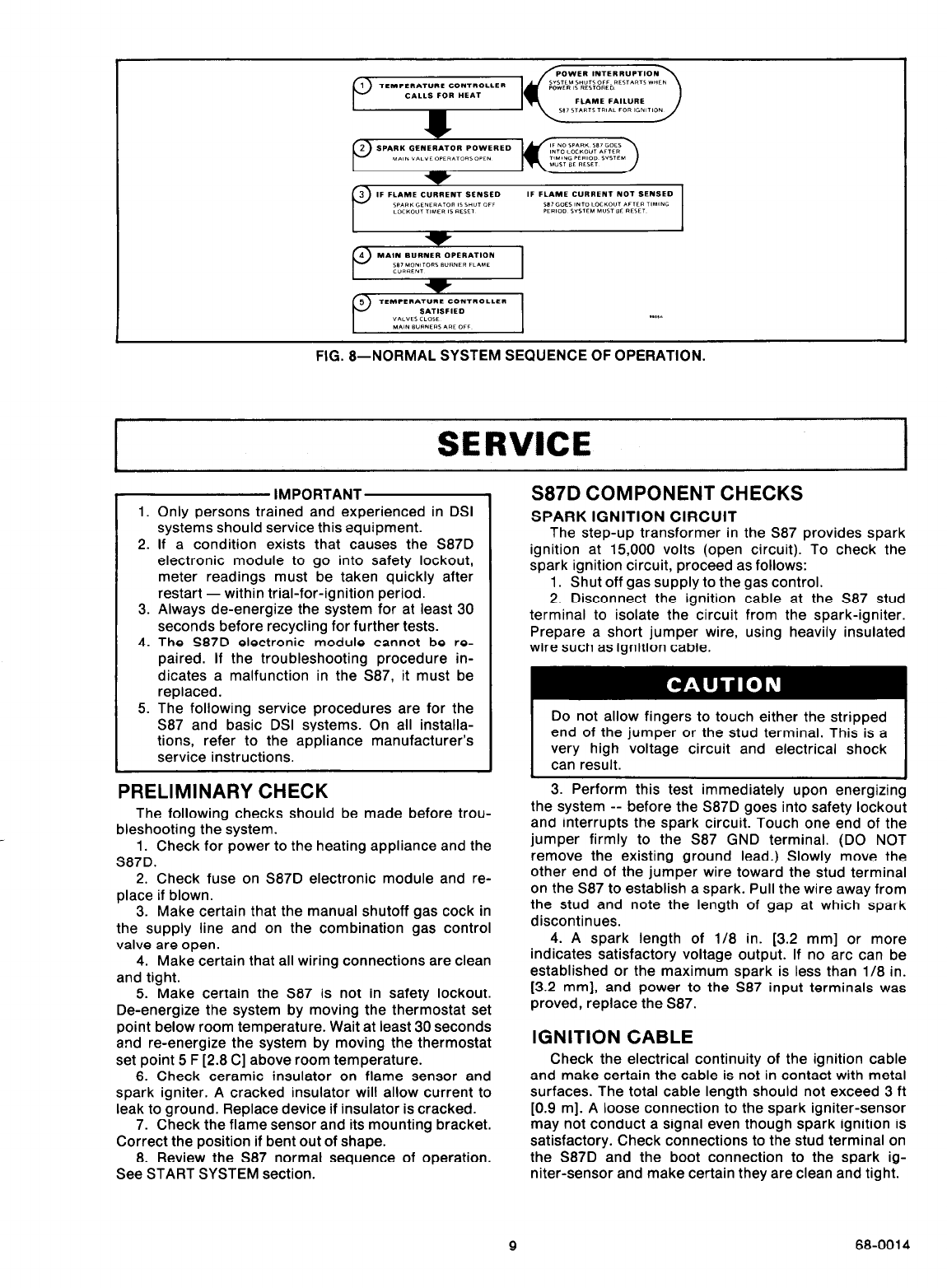
FIG. a--NORMAL SYSTEM SEQUENCE OF OPERATION.
SERVICE
l
Only persons trained and experienced in DSI
systems should service this equipment.
If a condition exists that causes the S87D
electronic module to go into safety lockout,
meter readings must be taken quickly after
restart - within trial-for-ignition period.
Always de-energize the system for at least 30
seconds before recycling for further tests.
The S87D electronic module cannot be re-
paired. If the troubleshooting procedure in-
dicates a malfunction in the S87, it must be
replaced.
The following service procedures are for the
S87 and basic DSI systems. On all installa-
tions, refer to the appliance manufacturer’s
service instructions.
1.
2.
3.
4.
5.
IMPORTANTLY
PRELIMINARY CHECK
The following checks should be made before trou-
bleshooting the system.
1. Check for power to the heating appliance and the
S87D.
2. Check fuse on S87D electronic module and re-
place if blown.
3. Make certain that the manual shutoff gas cock in
the supply line and on the combination gas control
valve are open.
4. Make certain that all wiring connections are clean
and tight.
5. Make certain the S87 is not in safety lockout.
De-energize the system by moving the thermostat set
point below room temperature. Wait at least 30 seconds
and re-energize the system by moving the thermostat
set point 5 F [2.8 C] above room temperature.
6. Check ceramic insulator on flame sensor and
spark igniter. A cracked insulator will allow current to
leak to ground. Replace device if insulator is cracked.
7. Check the flame sensor and its mounting bracket.
Correct the position if bent out of shape.
8. Review the S87 normal sequence of operation.
See START SYSTEM section.
S87D COMPONENT CHECKS
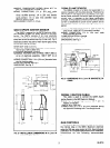
SPARK IGNITION CIRCUIT
The step-up transformer in the S87 provides spark
ignition at 15,000 volts (open circuit). To check the
spark ignition circuit, proceed as follows:
1. Shut off gas supply to the gas control.
2. Disconnect the ignition cable at the S87 stud
terminal to isolate the circuit from the spark-igniter.
Prepare a short jumper wire, using heavily insulated
wire such as ignition cable.
very high voltage circuit and electrical shock
3. Perform this test immediately upon energizing
the system -- before the S87D goes into safety lockout
and interrupts the spark circuit. Touch one end of the
jumper firmly to the 587 GND terminal. (DO NOT
remove the existing ground lead.) Slowly move the
other end of the jumper wire toward the stud terminal
on the S87 to establish a spark. Pull the wire away from
the stud and note the length of gap at which spark
discontinues.
4. A spark length of l/8 in. [3.2 mm] or more
indicates satisfactory voltage output. If no arc can be
established or the maximum spark is less than l/8 in.
[3.2 mm], and power to the S87 input terminals was
proved, replace the S87.
IGNITION CABLE
Check the electrical continuity of the ignition cable
and make certain the cable is not in contact with metal
surfaces. The total cable length should not exceed 3 ft
[0.9 m]. A loose connection to the spark igniter-sensor
may not conduct a signal even though spark ignition is
satisfactory. Check connections to the stud terminal on
the S87D and the boot connection to the spark ig-
niter-sensor and make certain they are clean and tight.
9
68-0014