


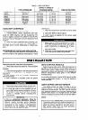
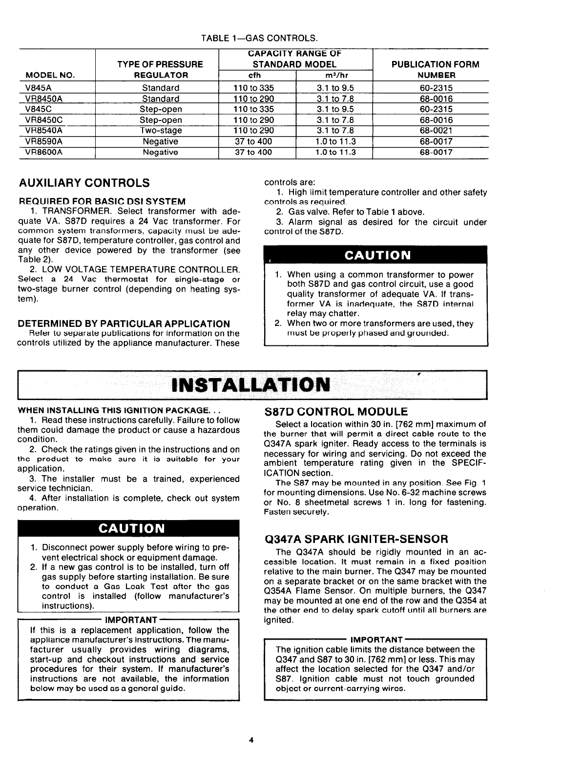
TABLE l-GAS CONTROLS.
MODEL NO.
V845A
VR8450A
V845C
VR8450C
VR8540A
VR8590A
VR8600A
TYPE OF PRESSURE
REGULATOR
Standard
Standard
Step-open
Step-open
Two-stage
Negative
Negative
CAPACITY RANGE OF
STANDARD MODEL
cfh
mJ/hr
110to335 3.1 to 9.5
110to290 3.1 to 7.8
11oto335 3.1 to 9.5
110to290 3.1 to 7.8
110to290 3.1 to 7.8
37 to 400 1.oto 11.3
37 to 400 1.oto11.3
PUBLICATION FORM
NUMBER
60-2315
68-0016
60-2315
68-0016
68-0021
68-0017
68-0017
AUXILIARY CONTROLS
REQUIRED FOR BASIC DSI SYSTEM
1. TRANSFORMER. Select transformer with ade-
quate VA. S87D requires a 24 Vat transformer. For
common system transformers, capacity must be ade-
quate for S87D, temperature controller, gas control and
any other device powered by the transformer (see
Table 2).
2. LOW VOLTAGE TEMPERATURE CONTROLLER.
Select a 24 Vat thermostat for single-stage or
two-stage burner control (depending on heating sys-
tem).
DETERMINED BY PARTICULAR APPLlCATiON
Refer to separate publications for information on the
controls utilized by the appliance manufacturer. These
controls are:
1. High limit temperature controller and other safety
controls as required.
2. Gas valve. Refer to Table 1 above.
3. Alarm signal as desired for the circuit under
control of the S87D.
1. When using a common transformer to power
both S87D and gas control circuit, use a good
quality transformer of adequate VA. If trans-
former VA is inadequate, the S87D internal
relay may chatter.
2. When two or more transformers are used, they
must be properly phased and grounded.
;NSlAL~~lON *
I
WHEN INSTALLING THIS IGNITION PACKAGE. . .
1. Read these instructions carefully. Failure to follow
them could damage the product or cause a hazardous
condition.
2. Check the ratings given in the instructions and on
the product to make sure it is suitable for your
application.
3. The installer must be a trained, experienced
service technician.
4. After installation is complete, check out system
operation.
1. Disconnect power supply before wiring to pre-
vent electrical shock or equipment damage.
2. If a new gas control is to be installed, turn off
gas supply before starting installation. Be sure
to conduct a Gas Leak Test after the gas
control is installed (follow manufacturer’s
instructions).
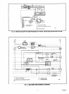
IMPORTANT
If this is a replacement application, follow the
appliance manufacturer’s instructions. The manu-
facturer usually provides wiring diagrams,
start-up and checkout instructions and service
procedures for their system. If manufacturer’s
instructions are not available, the information
below may be used as a general guide.
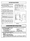
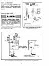
S87D CONTROL MODULE
Select a location within 30 in. [762 mm] maximum of
the burner that will permit a direct cable route to the
Q347A spark igniter. Ready access to the terminals is
necessary for wiring and servicing. Do not exceed the
ambient temperature rating given in the SPECIF-
ICATION section.
The S87 may be mounted in any position. See Fig. 1
for mounting dimensions. Use No. 6-32 machine screws
or No. 8 sheetmetal screws 1 in. long for fastening.
Fasten securely.
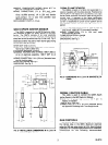
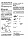
Q347A SPARK IGNITER-SENSOR
The Q347A should be rigidly mounted in an ac-
cessible location. It must remain in a fixed position
relative to the main burner. The CT347 may be mounted
on a separate bracket or on the same bracket with the
Q354A Flame Sensor. On multiple burners, the Q347
may be mounted at one end of the row and the Q354 at
the other end to delay spark cutoff until all burners are
ignited.
Q347 and S87 to 30 in. [762 mm] or less. This may
affect the location selected for the 0347 and/or
S87. Ignition cable must not touch grounded