


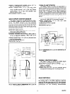
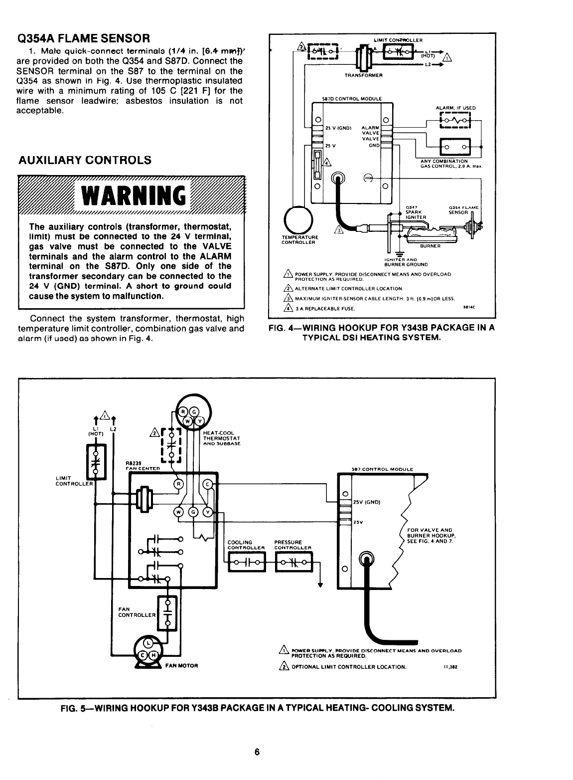
Q354A FLAME SENSOR
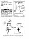
1. Mate quick-connect terminals (l/4 in. [6.4 mmf)’
are provided on both the Q354 and S87D. Connect the
SENSOR terminal on the 587 to the terminal on the
Q354 as shown in Fig. 4. Use thermoplastic insulated
wire with a minimum rating of 105 C [221 F] for the
flame sensor leadwire; asbestos insulation is not
acceptable.
AUXILIARY CONTROLS
The auxiliary controls (transformer, thermostat,
limit) must be connected to the 24 V terminal,
gas valve must be connected to the VALVE
terminals and the alarm control to the ALARM
terminal on the S87D. Only one side of the
transformer secondary can be connected to the
24 V (GND) terminal. A short to ground could
cause the system to malfunction.
Connect the system transformer, thermostat, high
temperature limit controller, combination gas valve and
alarm (if used) as shown in Fig. 4.
FIG. 4-WIRING HOOKUP FOR Y343B PACKAGE IN A
TYPICAL DSI HEATING SYSTEM.
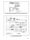
IOTOR
PRESSURE
FOR VALVE AN0
WRNER HOOKUP.
SEE FIG. 4 AND 7.
n
1 POWER SUPPLY. PROVIDE 01SCONNECT MEANS AND OVERLOAD
PROTECTlON AS REQVIRED.
n
2 OPTIONAL LlMlT CONTROLLER l_OCATION.
I I .3*1
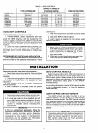
FIG. 6-WIRING HOOKUP FOR Y343B PACKAGE IN A TYPICAL HEATING- COOLING SYSTEM.
6