


GROUNDING CONNECTIONS
A common ground is required for the burner, spark
igniter-sensor mounting bracket and the GND terminal
of the 587. If ground is poor or erratic, safety shutdown
may occur occasionally even though operation is nor-
mal at time of checkout. Therefore, if nuisance shut-
downs have been reported, be sure to check ground
connections.
Electrical ground connections at the spark ig-
niter-sensor and the S87D must be clean and tight. If
leadwire is damaged or deteriorated, use only No. 14 or
No. 18 gauge, moisture-resistant, thermoplastic in-
sulated wire with 105 C [221 F] minimum rating as
replacement.
FLAME SENSOR CIRCUIT
The S87D provides ac power to the flame sensor
which the burner flame rectifies to direct current. If the
flame signal back to the S87 is not at least 1.5 uA dc, the
system will lock out.
The output of the flame sensing circuit can be
checked directly on the S87D. Check the flame sensing
circuit as follows.
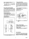
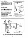
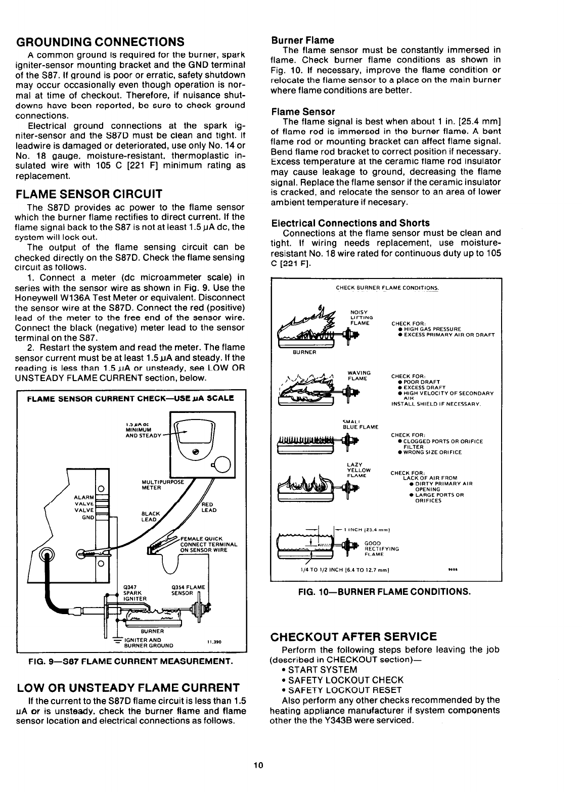
1. Connect a meter (dc microammeter scale) in
series with the sensor wire as shown in Fig. 9. Use the
Honeywell Wl36A Test Meter or equivalent. Disconnect
the sensor wire at the S87D. Connect the red (positive)
lead of the meter to the free end of the sensor wire.
Connect the black (negative) meter lead to the sensor
terminal on the S87.
2. Restart the system and read the meter. The flame
sensor current must be at least 1.5uA and steady. If the
reading is less than 1.5 uA or unsteady, see LOW OR
UNSTEADY FLAME CURRENT section, below.
FLAME SENSOR CURRENT CHECK-USE YA SCALE
FIG. g-S87 FLAME CURRENT MEASUREMENT.
LOW OR UNSTEADY FLAME CURRENT
If the current to the S87D flame circuit is less than 1.5
AIA or is unsteady, check the burner flame and flame
sensor location and electrical connections as follows.
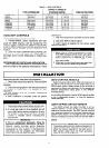
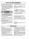
Burner Flame
The flame sensor must be constantly immersed in
flame. Check burner flame conditions as shown in
Fig. 10. If necessary, improve the flame condition or
relocate the flame sensor to a place on the main burner
where flame conditions are better.
Flame Sensor
The flame signal is best when about 1 in. [25.4 mm]
of flame rod is immersed in the burner flame. A bent
flame rod or mounting bracket can affect flame signal.
Bend flame rod bracket to correct position if necessary.
Excess temperature at the ceramic flame rod insulator
may cause leakage to ground, decreasing the flame
signal. Replace the flame sensor if the ceramic insulator
is cracked, and relocate the sensor to an area of lower
ambient temperature if necesary.
Electrical Connections and Shorts
Connections at the flame sensor must be clean and
tight. If wiring needs replacement, use moisture-
resistant No. 18 wire rated for continuous dutv up to 105
_
C [221 F].
FIG. lo--BURNER FLAME CONDITIONS.
CHECKOUT AFTER SERVICE
Perform the following steps before leaving the job
(described in CHECKOUT section)-
* START SYSTEM
l SAFETY LOCKOUT CHECK
. SAFETY LOCKOUT RESET
Also perform any other checks recommended by the
heating appliance manufacturer if system components
other the the Y343B were serviced.
10