


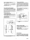
Position the Q347 so that only the tips of the elec-
trodes are immersed in the burner flame. The burner
must ignite smoothly - usually this will be ac-
complished with tip of electrodes (spark gap) spaced
approximately l/4 in. [6.4 mm] from the surface of the
burner. Gas must flow into one of the three open sides
of the spark gap (where outer electrode does not block
gas). The center electrode must not be near any
ground.
The spark gap is factory-adjusted to 5/32 in. [4 mm].
If this setting is disturbed in shipment or installation,
readjust by carefully bending the bent tip of the ground
(outer) electrode only.
Q354A FLAME SENSOR
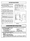
The Q354 should be rigidly mounted in an accessible
location. It must remain in a fixed position relative to the
main burner. Mount the Q354 on a separate bracket or
on the same bracket with the Q347 Spark Igniter.
Tip of rod must be immersed in main burner flame.
Depth of immersion (usually about 1 in. [25.4 mm]) and
distance from rod to burner surface (usually l/4 in. [6.4
mm]) depends on type of burner and flame configura-
tion. Position selected must produce sensor current of
1.5 microamperes (minimum). See Fig. 9, Page 10, to
measure current.
The main burner serves as the grounding area for
the flame signal. Install ground wire from the main
burner to the ground terminal of the S87D.
AUXILIARY CONTROLS
1. If a common transformer is used to power both
the S87D and the burner valve circuit, its
capacity (VA) must be adequate for all of the
system components (see Table 2).
2. Turn off gas supply before beginning installa-
tion. After installing gas control, be sure to
conduct Gas Leak Test, page 8.
Install the auxiliary controls required in the complete
control system, following the instructions of the ap-
pliance or control manufacturer.
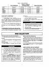
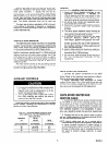
TABLE 2-TRANSFORMER RATINGS FOR
S87D AND DUAL VALVE COMBINATION
GAS CONTROL.
MINIMUM
TOTAL
VA
VALVE
RATING
CURRENT
(24 V transformer)
(in amperes)
S87D
CURRENT
(in amperes)
20 Up to 0.6 0.2
30 0.7 to 1 .o 0.2
40 1.1 to 1.4 0.2
55 1.5 to 2.0 0.2
WIRING
GENERAL PRECAUTIONS’-f
1.
2.
3.
4.
5.
6.
7.
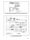
Check the wiring diagram furnished by the
appliance manufacturer, if available, for
circuits differing from the ones shown in this
publication. Carefully follow all instructions af-
fecting the general procedures outlined below.
All wiring must comply with applicable elec-
trical codes and ordinances.
Disconnect the power supply before wiring to
prevent electrical shock and equipment
damage.
The flame sensor leadwire should be kept as
short as possible and should not be allowed to
rest against grounded metal surfaces.
A common ground is required for the S87D
Electroic Module, Q347A Spark lg-
niter-Sensor, Q354A Flame Sensor and main
burner. The S87 ground (GND) terminal in-
ternally grounds one side of the transformer.
Any auxiliary controls or limits used must not
be in the grounded leg.
Ignition cable should not touch any metal sur-
face or current-carrying wires. It must not be
more than 30 in. 1762 mm] long.
Do not short valve terminals as this may burn
out the temperature controller or the
transformer.
S87D CONTROL MODULE
1. Connect the system components to the S87D
quick-connect terminals as shown in the wiring dia-
grams. Refer to the appliance manufacturer’s instruc-
tions for wiring any other auxiliary controls.
2. Adjust thermostat heat anticipator to match
system current draw. The current draw equals the total
current required for the S87D (0.2 A) plus the gas valve.
Gas valve must be designed for DSI application.
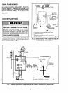
Q347A SPARK IGNITER AND
IGNITION CABLE
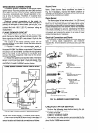
1. Connect the GND burner, quick-connect terminal
on the S87D to one of the mounting screws on the
Q347A as shown in Fig. 4. The S87 and Q347 must have
a common ground. Use thermoplastic insulated wire
with a minimum rating of 105 C [221 F] for the ground
wire; asbestos insulation is not acceptable. If neces-
sary, use a shield to protect the wire from radiant heat
generated by the burner.
2. Connect one end of the ignition cable (supplied
with the Y343B package) to the ignition terminal on the
S87 and the other end to the Q347.
NOTE: Ignition cable must not run in contact with a
metal surface or current-carrying wires. Use ceramic
or plastic standoff insulators to protect voltage to
spark electrode from being reduced. If cable passes
through a metal panel, use an insulated bushing in
the panel to prevent voltage reduction to spark
electrode.
5
68-0014