


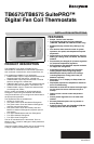
TB6575/TB8575 SUITEPRO™ DIGITAL FAN COIL THERMOSTATS
7 62-0278—07
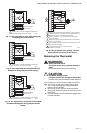
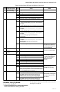
Thermostat Wiring Diagrams
The figures in this section illustrate typical wiring for:
• TB6575A1000, TB6575B1000 and TB6575C1000 fan
coil thermostats, which are 120/240/277 Vac powered.
Refer to Fig. 7–Fig. 13, beginning on page 7,
• TB8575A1000 model, which is 24 Vac powered. Refer
to Fig. 14–Fig. 20, beginning on page 8.
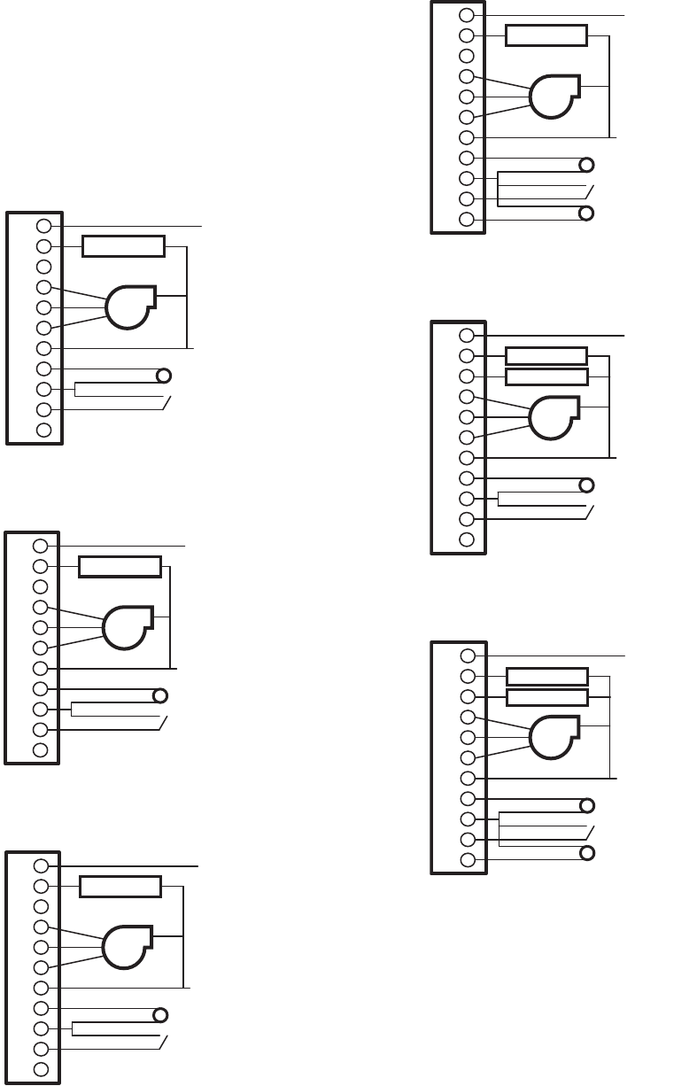
120/240/277 Vac Wiring Diagrams
(TB6575A/B/C)
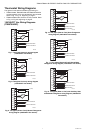
Fig. 7. Two pipes Heat-only wiring diagram
(120/240/277 Vac shown).
Fig. 8. Two pipes Cool-only wiring diagram
(120/240/277 Vac shown).
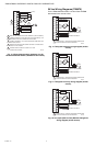
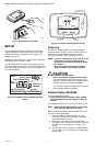
Fig. 9. Two pipes (Heat or Cool) Manual Changeover
wiring diagram (120/240/277 Vac shown).
Fig. 10. Two pipes (Heat or Cool) Auto Changeover
wiring diagram (120/240/277 Vac shown).
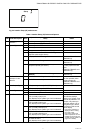
Fig. 11. Four pipes (Heat and Cool) Manual/Auto
changeover wiring diagram (120/240/277 Vac shown).
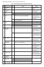
Fig. 12. Two pipes (Heat or Cool) with Auxiliary Heat
and Manual Changeover wiring diagram (120/240/277
Vac shown).
L
W/Y
Y/A
GI
Gm
Gh
N
Rs
Sc
SB
Ps
N
L (HOT)
M27566
REMOTE SENSOR
REMOTE SETBACK
HEAT VALVE
FAN
N
L (HOT)
M27567
REMOTE SENSOR
REMOTE SETBACK
COOL VALVE
FAN
L
W/Y
Y/A
GI
Gm
Gh
N
Rs
Sc
SB
Ps
N
L (HOT)
M27568
REMOTE SENSOR
REMOTE SETBACK
VALVE
FAN
L
W/Y
Y/A
GI
Gm
Gh
N
Rs
Sc
SB
Ps
N
L (HOT)
M27569
REMOTE SENSOR
REMOTE SETBACK
VALVE
FAN
PIPE SENSOR
L
W/Y
Y/A
GI
Gm
Gh
N
Rs
Sc
SB
Ps
N
L (HOT)
M27570
REMOTE SENSOR
REMOTE SETBACK
HEAT VALVE
FAN
COOL VALVE
L
W/Y
Y/A
GI
Gm
Gh
N
Rs
Sc
SB
Ps
N
L (HOT)
M27571
REMOTE SENSOR
REMOTE SETBACK
VALVE
FAN
AUX
PIPE SENSOR
L
W/Y
Y/A
GI
Gm
Gh
N
Rs
Sc
SB
Ps