


TB6575/TB8575 SUITEPRO™ DIGITAL FAN COIL THERMOSTATS
62-0278—07 12
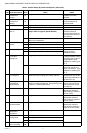
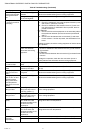
6 Pipe Sensor
Threshold for
Cooling
50 to
72
Range is 50°F to 72°F. Default is 60°F. Changes to Cool when pipe
temperature is below
threshold.
7 Pipe Sensor
Threshold for
Heating
75 to
90
Range is 75°F to 90°F. Default is 80°F. Changes to Heat when pipe
sensor temperature is
above threshold.
8 Temperature Scale 0 Degrees Fahrenheit (°F); Default.
1 Degrees Celsius (°C).
8.5 Fan Speed at motor
start up
0 Provide full power when fan motor starts –
always starts in high fan speed (Default)
High speed start up
ensures that there is
enough torque to start the
motor and eliminates and
motor locking.
1 Disable – fan will start at speed that is needed as
defined by VersaSpeed
9 Number of Fan
Speeds
1 Single Speed Fan Low speed only
2 2 Speed Fan Hi and Low speed fans only
3 3 Speed Fan (Default) Hi, Med, and Low speed fan
9.5 Fan Control Type 0 Constant and Auto (Default) When fan is in Auto, the fan
ramping algorithm,
Veraspeed, is used
1 Auto only
10 Control Method for
4-Pipe Auto
Changeover
1 Single Setpoint (Default) Uses switching differential
to change between heating
and cooling and controls to
a single setpoint (Only
displayed for system types
5 or 7)
2 Heat and Cool Setpoints (2 setpoint method) Uses a deadband of no
control and controls to a
heat or cool setpoint. (Only
displayed for system types
5 or 7)
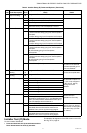
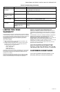
10.5 Deadband for Heat/
Cool Setpoints
2 to 9 Range is 2 to 9. Default is 3. Deadband = minimum
distance between heating and cooling setpoints.
Available when Heat and
Cool Setpoints are chosen
for the control method for 4-
pipe Auto (ISU 10)
Switching
Differential for
Single Setpoint
2 to 6 Range is 2 to 6. Default is 3. Heat switching point =
setpoint - switching differential. Cool switching point
= setpoint + switching differential.
Available when Single
Setpoint is chosen for the
control method for 4-pipe
Auto (ISU 10)
11 CPH Value for Heat 1 to 12 Range is 1 to 12. Default is 4. The number selected
indicates the maximum
times Heating is cycled on
per hour (CPH).
12 CPH Value for Cool 1 to 6 Range is 1 to 6. Default is 3. The number selected
indicates the maximum
times Cooling is cycled on
per hour (CPH).
13 CPH for Auxiliary
Electrical Heater
1 to 12 Range is 1 to 12. Default is 6. The number selected
indicates the maximum
times Auxiliary Heating is
cycled on per hour (CPH).
14 Display
Temperature
Adjustment
-4 to 4 Range is -4°F to +4°F; Default is 0°F
.
15 Temperature
Display Mode
0 Display Room Temperature
1 Display Setpoint
2 Display Temperature and Setpoint; Default.
16 Setpoint Range
Stop for Heating
50 to
90
Range is 50°F to 90°F. Default is 90°F.
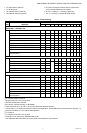
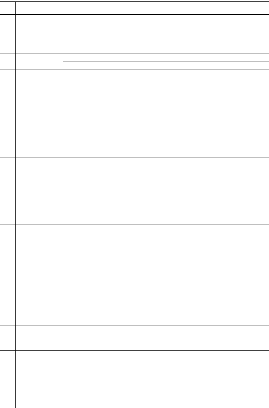
Table 4. Installer Setup (IS) Codes and Options. (Continued)
IS
Code Code Description
Option
Value
Option Description (Default value shown in
Bold) Notes