


TB6575/TB8575 SUITEPRO™ DIGITAL FAN COIL THERMOSTATS
62-0278—07 2
SPECIFICATIONS
Supply Voltages:
TB6575A1000 and TB6575B1000:
• 120 Vac ±10% at 50/60Hz
• 240 Vac -15% to +10% at 50/60Hz
TB6575C1000:
• 120/240/277 Vac ±10% at 50/60Hz
TB8575A1000:
• 20 to 30 Vac at 50/60Hz (using 24 Vac, Class 2,
NEMA rated transformer)
Safety Fuse: TB6575A1000 and TB6575B1000 use 15A
250 Vac fuse. TB6575C1000 uses a 15A 350 Vac fuse.
If the safety fuse blows, the thermostat must be
replaced. The fuse is not field replaceable.
Electrical Ratings: (see Table 1).
Environmental Ratings:
Temperature:
Operating Range: 18°C to 49°C (0°F to 120°F).
Shipping and Storage Range: -29°C to 49°C (-20°F to
120°F).
Humidity: 5% to 90% RH, non-condensing.
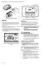
Onboard Temperature Sensor:
Type: 10K NTC
Working Range: 18°C to 49°C (0°F to 120°F)
Display Range: 0°C to 37°C (32°F to 99°F)
Accuracy ±2.0°F at 70°F
Remote Temperature Sensor (optional):
Type: 20K NTC
Working Range: 18°C to 49°C (0°F to 120°F)
Display Range: 0°C to 37°C (32°F to 99°F)
Accuracy ±2.0°F at 70°F
Remote Pipe Sensor (optional):
Type: 20K NTC
Working Range: 0°C to 93°C (32°F to 199°F)
Display Range: 0°C to 93°C (32°F to 199°F)
Accuracy ±5.0°F over the temperature sensing range
Remote Setback Input: Dry contact, maximum
resistance of 100 ohms. TB6575 – 9Vdc, < 4 mA; TB8575
– 16 Vdc, < 5 mA. Note Electrical WARNING on page 3.
Remote Setback Range:
Heating: 10°C to 21°C (50°F to 70°F).
Cooling: 22°C to 32°C (72°F to 90°F).
Enclosure: Plastic (cover, sub-base, and optional adap-
tor plate)
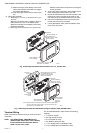
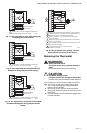
Junction Box Mounting: Direct mounting on a horizontal
single gang NEMA 2 x 4 in. surface mount electrical box,
or on 4 x 4 in. box or vertical 2 x 4 in. surface mount
electrical box with the optional 50033847-001 adapter
plate.
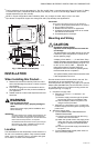
Dimensions: See Fig. 1 on page 3.
Wiring: 11 screw-in terminals located on the sub-base
capable of accepting up to 2 x 18 AWG (0.8 sq. mm), 1 x
16 AWG (1.3 sq. mm), or 1 x 14 AWG (2.1 sq. mm) wires.
Accepts stranded or unstranded 14-28 gauge wire.
NOTES:
1. The TB6575A1000 and TB6575C1000 models
are pre-fitted with color-coded fly leads (16
AWG) attached to seven terminals.
2. The TB6575B1000 model is pre-fitted with color-
coded fly leads (16 AWG) attached to six
terminals.
3. The TB8575A1000 model does not have fly
leads attached to any terminals.
4. See Table 3 on page 5 for fly lead usage.
Minimum Operational Life (at maximum load):
Thermostat contacts: 100,000 cycles
Approvals:
CSA Certified C/US for Canada and the U.S.A. Meets
the same requirements as UL-873.
FCC Part 15 Class B
Accessories:
• 50033847-001 – Adapter plate for mounting on a
vertical 2 x 4 in. single-gang or double-gang NEMA
standard vertical switch box (6 1/4 in. (158 mm) x 5 1/
16 in. (128 mm) x 13/22 in. (10 mm)).
• TR21 – 20K Ohm NTC Non-Linear Remote
temperature sensor.
Other acceptable remote temperature sensors are —
• 20K Ohm: C7041B2005, C7041B2013, C7041C2003,
C7041P2004, C7770A1006, C7772A1004, and
C7772A1012
• 10K Ohm (for averaging only): TR21-A
• PS20 – Remote pipe sensor (20K Ohm)
• W6380B1005 – Fan Coil Unit Relay Control Center
• WSK-24 - Wireless Occupancy Solution (Receiver,
occupancy sensor and door sensor)
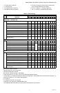
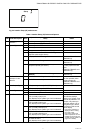
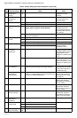
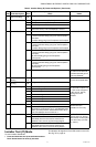
Models, applications, and features:
Table 2 identifies the applications and features of each model.
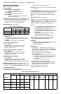
Table 2. Applications and Features
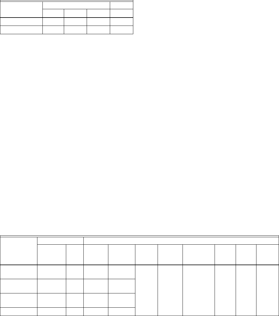
Table 1. Electrical Ratings.
Component
Amps (inductive) for:
24 Vac 120 Vac 240 Vac 277 Vac
Fan Relay 1.0 A 6.0 A 3.0 A 2.4 A
Heat/Cool Relay 1.0 A 1.0 A 1.0 A 1.0 A
Models
Applications Features
Heat/Cool/
Auto
Pipes Voltage Number
of Relays
a
Energy
Savings
Input
Fan: On,
Auto, or 3
speed
Manual/
Auto
Changeover
Remote
Sensor
Back
Light
Pipe
Sensor
b
TB6575A1000 All 2 or 4 120 or
240 Vac
5
Ye s Ye s Ye s Ye s Ye s Ye s
TB6575B1000 Heat or
Cool
2 120 or
240 Vac
4
TB6575C1000 All 2 or 4 120/240/
277 Vac
5
TB8575A1000 All 2 or 4 24 Vac 5