


TB6575/TB8575 SUITEPRO™ DIGITAL FAN COIL THERMOSTATS
17 62-0278—07
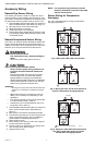
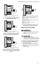
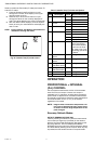
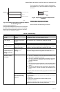
Fig. 29. 4 Pipe Auto Changeover with Single Setpoint
and Switching Points
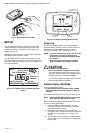
Heat/Cool Setpoint Method
In 4 pipe auto changeover with heat and cool setpoints,
the system key is used to switch between the heating
setpoint and cooling setpoints. Use the Up and Down
arrow buttons to change the setpoint.
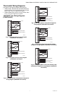
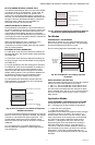
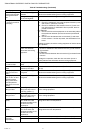
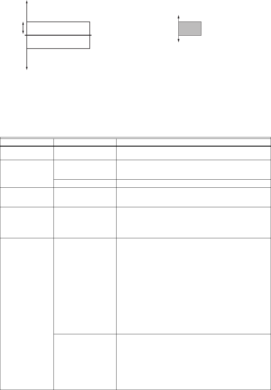
For this application, the setpoint settings and deadband
are illustrated in Fig. 30. The deadband is changed via IS
code #10.
Fig. 30. 4 Pipe Auto Changeover setpoints and
deadband.
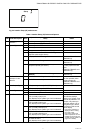
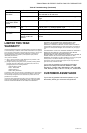
TROUBLESHOOTING
Table 8 provides troubleshooting information.
M31330
HEAT SWITCHING POINT
COOL SWITCHING POINT
SWITCHING
DIFFERENTIAL
SETPOINT
DEADBAND
COOLING SETPOINT
HEATING SETPOINT
M27565
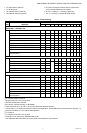
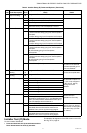
Table 8. Troubleshooting.
Symptom Possible Cause Action
Display does not
come on.
Thermostat is not being
powered.
For TB6575A/B/C, check for 120/240/277 Vac between L and N.
For TB8575A, check for 24 Vac between R and C.
Temperature settings
do not change.
The upper or lower
temperature limits were
reached.
Check the temperature setpoints for heating and cooling (Installer
Setup codes 16 and 17 respectively). Modify as needed.
The keypad is fully locked. Change keypad locked options (Installer Setup code #18).
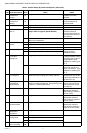
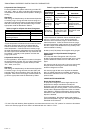
Heating or cooling
does not come on.
System Type selection not
set to Heat or Cool or the
selection is incorrect.
Set the Installer Setup code #2 (System Type) to the correct value
to match the installed heating and/or cooling equipment. Verify
operation of wiring and equipment in Installer Test mode.
Thermostat is calling
for Heat (Heat on) or
Cool (Cool on) but no
heating or cooling is
running.
Heating or cooling
equipment is not
operating.
Check wiring. Check that the Installer Setup code #2 (System
Type) value matches the installed heating and/or cooling
equipment. Verify operation of equipment in Installer Test mode.
Heat does not turn on
(Heat On is solid in
the display).
Heating equipment failure. For TB6575A/B/C:
1. Check for 120/240/277 Vac at the equipment between power
and common, (terminals L and N).
2. Check for 120/240/277 Vac between the heat (W) and com-
mon (N) terminals. If 120/240/277 Vac is present, the ther-
mostat is functional.
For TB8575A:
1. Check for 24 Vac at the equipment on the secondary side of
the transformer between power and common (terminals R
and C).
2. Check for 24 Vac between the heat terminal (W) and trans-
former common. If 24 Vac is present, the thermostat is func-
tional.
If voltage is present, check the heating equipment to find the cause
of the problem.
Loose connection or
broken wire between
thermostat and heating
equipment.
For TB6575A/B/C:
Check for 120/240/277 Vac between the heat (W) and common
(N) terminals.
For TB8575A:
Check for 24 Vac between the heat terminal (W) and
transformer common.
If voltage is not present, check wire connection (loose or broken)
between the thermostat and the heating equipment.