


TB6575/TB8575 SUITEPRO™ DIGITAL FAN COIL THERMOSTATS
62-0278—07 6
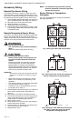
Accessory Wiring
Remote Pipe Sensor Wiring
The remote pipe sensor is used for 2 pipes auto and 2
pipes heat and cool with auxiliary heat changeover. The
pipe sensor will sense the temperature in the pipes to tell
the thermostat when the system is set for Heat or Cool.
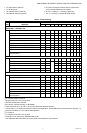
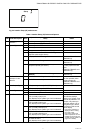
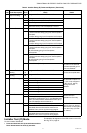
1. Check Installer Setup Number (ISU) 5 to ensure it is
set to the desired value. (See Table 4 on page 11).
2. Wire pipe sensor to Sc and Ps terminals.
3. Attach pipe sensor to the pipe.
4. Insulate pipe sensor, as necessary.
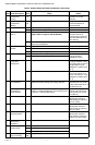
5. Change pipe sensor thresholds for cooling or heat-
ing by setting Installer Setup Numbers (ISU) 6 and
7 to desired values.
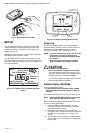
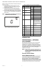
Remote Temperature Sensor Wiring
The TR21 is an optional remote temperature sensor that
can be used as an alternative to the internal sensor. In
addition to the TR21, other Honeywell sensors that use a
20k Ohm curve may be used as the remote sensor.
WARNING
Risk of electrical shock.
Can cause severe injury, property damage or
death.
Disconnect power supply before servicing.
CAUTION
Erratic system operation hazard.
Failure to follow proper wiring practices can
introduce disruptive electrical interference
(noise).
Keep wiring at least one foot away from large
inductive loads such as motors line starters,
lighting ballasts, and large power distribution
panels. Shielded cable is required in installations
where these guidelines cannot be met. Ground
shield only to grounded controller case.
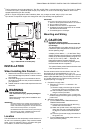
IMPORTANT
All wiring must comply with local electrical codes and
ordinances or as specified on installation wiring dia-
grams.
— Wall module wiring can be sized from 16 to 22
AWG (1.31 to 0.33 sq. mm) depending on the
application.
— The maximum length of wire from the thermostat
to a wall module is 1000 ft. (305 m).
— Twisted pair wire is recommended for wire runs
longer than 100 ft. (30.5 m).
1. Check Installer Setup Number (ISU) 4 to ensure it is
set to use the remote sensor. (See Table 4 on
page 11).
2. Wire sensor to Rs and Sc thermostat terminals.
3. Push excess wire back into the hole. Plug the hole
using non-hardening caulk, putty or insulation to
prevent drafts from affecting performance.
4. Remove sensor cover.
5. Mount sensor to the wall or junction box using the
screws and anchors provided.
6. Level the sensor for appearance only. Device func-
tions correctly even when not level.
7. Replace sensor cover.
NOTE: For complete wiring instructions, please
follow the installation instructions provided
with the remote sensor.
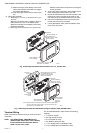
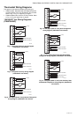
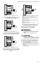
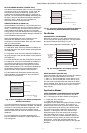
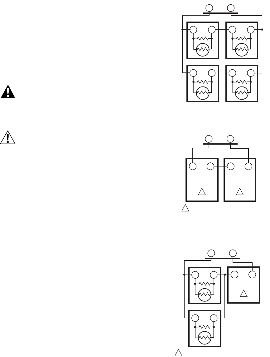
Sensor Wiring for Temperature
Averaging
Fig. 4–Fig. 6 illustrate sensor wiring for temperature
averaging applications.
Fig. 4. Wiring four TR21 (20K ohm) sensors.
Fig. 5. Wiring two TR21-A (10K ohm) sensors to
provide a temperature averaging network.
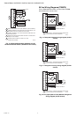
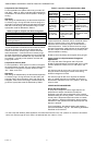
Fig. 6. Wiring two TR21 (20K ohm) sensors and
one TR21-A (10K ohm) sensor to provide
a temperature averaging network.
M27559
Rs Sc
T T
SUBBASE
TR21
T T
TR21
T T
TR21
T T
TR21
M27560
Rs
Sc
SUBBASE
TR21-A
T4 T3
TR21-A
T4 T3
1
11
THE TR21-A IS A 10K OHM SENSOR.
M27561
T4
T3
TR21-A
1
1
THE TR21-A IS A 10K OHM SENSOR.
Rs
Sc
T
T
SUBBASE
TR21
TT
TR21