


R7426A,B,C TEMPERATURE CONTROLLER WITH AND WITHOUT REAL TIME CLOCK
9 EN1B-0203GE51 R0507C
limit or cascade sensor (T2) to operate the output device from
full open (100%) to full closed (0%) or vice versa.
Xp1 is the throttling range for the main control loop, Xp2 is
used if limitation or cascade control (submaster control loop)
is active (see Table 11).
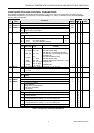
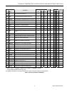
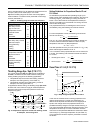
Table 11. Throttling range and reset time reference
application sens.
Xp1 Xp2 Xpc Xph
tr1 tr2
R7426A Controller
Main Temp.Control T1 x x
High or Low Limit
Temperature Control
T2 x x
Cascade Control
Master T1 x x
Submaster T2 x x
R7426B,C Controller
Main Temp. Seq. Control
Mixed Air Damper T1 x x
Energy Recovery T1 x x
Heating T1 x x
Cooling T1 x x
R7426B,C Controller
Temperature Cascade
Sequence Control
Master T1 x x
Submaster
- Mixed Air Dampers T2 x x
- Energy Recovery T2 x x
- Heating T2 x x
- Cooling T2 x x
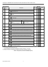
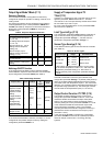
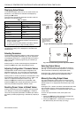
Throttling Range Xpc / Xph (P.10 / P11)
The control parameters Xpc and Xph are only available on
R7426B,C controllers and are used to set the cooling and
heating throttling ranges for the following applications
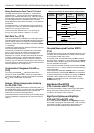
• Temperature sequence control with heating, mixed air
dampers, and cooling (see Fig. 3 and Table 11)
• Temperature cascade control with heating, mixed air
dampers, and cooling (see Table 11)
In applications without cooling, the throttling range Xpc must
be set to OFF 100% fresh air supply at actual temperature
above the control point is required (outdoor and return air
dampers fully open).
T2
100
0
Xpc
Cooling
Heating
CTRP1
Xwh / Xwc
Xph
CTRPC
CTRPH
Xp1
Damper
Y[%]
MINPOS
Xwd
/
1/4 Xp1 if Xpc = Off
if Xpc = Off
Y1
Y3
Y2
Fig. 3. Temperature sequence control with heating, mixed
air dampers, and cooling valve
Setting Guidelines for Proportional Band of P and
P+I Control
To estimate the proportional band (throttling range X
p
) for
stable control under all different load conditions, the control or
correcting range X
h
of the heating or cooling coil must be
known. This is the maximum air temperature increase pro-
duced by the heating coil or decrease of a cooling coil if the
control valve is fully open.
The proportional band X
p
for discharge air control can be
calculated by using the following rule-of thumb formula:
X
p
=
X
h
5
For room temperature control, the following rule-of-thumb
formula can be used:
X
p
=
X
h
10
or
∆t discharge air
max
10
The ∆t
max
(X
h
) of the discharge air for mixed air damper con-
trol is the maximum difference between outdoor air (OA)
temperature and return air (RA) temperature.
X
h
= ϑ
RA
- ϑ
OAmin
The often-specified accuracy for room control of ±1 (X
p
= 2K)
allows a discharge air alteration of 20 °C.
In P+I control the same proportional band can be used as for
P control. The following rule-of-thumb formulae are used for
P+I control:
• Discharge air control
X
p
=
X
h
45...
• Room control
X
p
=
X
h
810...
or
∆t discharge air
8 ... 10
max
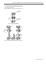
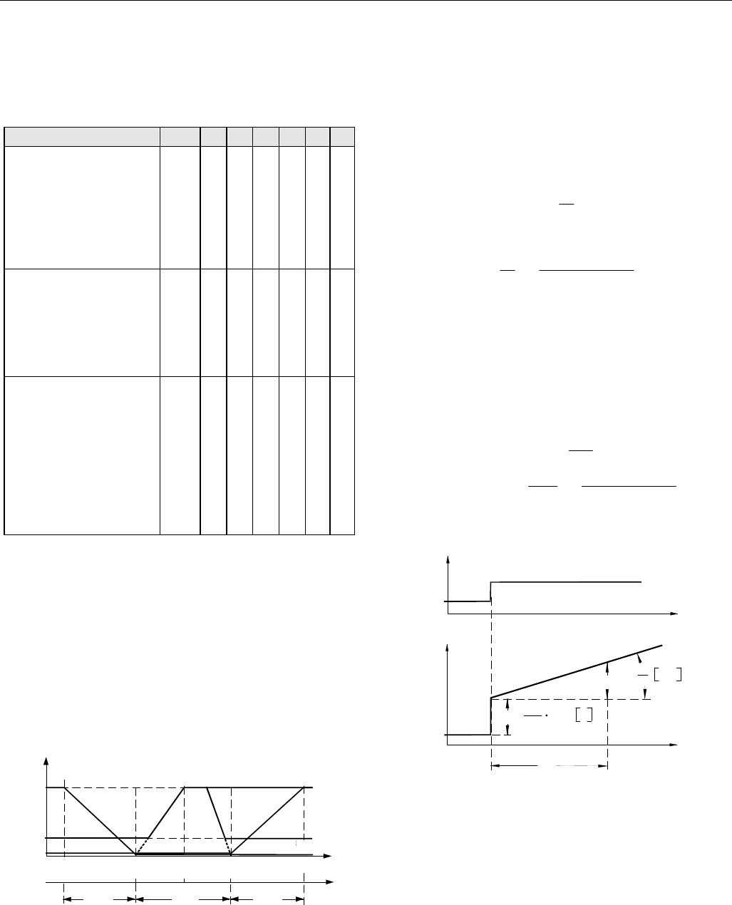
Reset Time tr1 / tr2 (P.12 / P13)
P
P
tr
%/s
t
t
Y
X
w
tr
0
P =
100
X
p
X
w
%
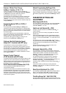
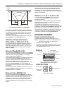
Fig. 4. Step change response of P+I control
In the case of combined action including proportional and
integral components (P+I control), the reset time (tr) is
defined as the required time after which the integral part is
equal to the change due to the proportional action for a
predetermined step change in the input variable. See Fig. 4.
The control parameter tr1 sets the reset time of the P+I main
temperature control loop. For limit or submaster cascade
control the control parameter tr2 sets the reset time of these
control loops, e.g. discharge temperature T2 (see Table 11).
If only proportional control is required, parameter tr must be
set to OFF.