


R7426A,B,C TEMPERATURE CONTROLLER WITH AND WITHOUT REAL-TIME CLOCK
EN1B-0203GE51 R0507C 6
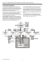
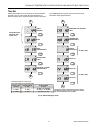
CONFIGURATION SETTINGS
The controllers R7426A,B are supplied with unconfigured
outputs to avoid damage of installed final control devices by
supply of not applicable output signals if the controller power
supply is turned on.
All configuration parameters must be set to select the correct
control functions as required for the job application and to
start control operation and synchronization of the final control
devices.
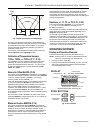
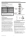
Direct - Reverse Action
Dir/Revx, x = Y1, Y2 or Y3 (C.01...C.03)
The output action of the analog outputs on the R7426C
controller must sometimes be reversed for a correct opening
and closed direction of the valve or damper. This depends on
whether the output controls a 2-way or 3-way valve or on the
direction the damper shaft moves to open the damper (cw or
ccw). It is needed only if the actuator does not provide a
direction selector switch, plug, or similar.
In the case of the R7426A,B controllers, the direction can be
changed by exchanging the wiring connections open-close
(OUT2-OUT1).
Operating Range Selection Ctrltyp (C.04)
The controllers provide two operating ranges which can be
selected by the configuration parameter Ctrltyp
(Lo = 0...50°C, Hi1/Hi2 = 0...130°C).
Depending on this parameter setting, the setpoint ranges for
the main temperature (W1), limit temperature (W
lim
), and
submaster temperature (W
cas
) are selected for air tem-
perature applications (Ctrltyp = Lo) or for flow water
temperature applications (Ctrltyp = Hi1/Hi2).
If the configuration parameter Ctrltyp = Hi1, normal operation
for flow water application will be performed. If Ctrltyp = Hi2,
the following additional function will be active on controllers
with real-time clock:
The controller switches the ON/OFF output (e.g. the pump)
from ON to OFF if
- the outside air temperature is above 8°C and
- the output signal Y1 = 0% for more than 5 minutes during
the controller is in the Comfort, Standby, or Night mode.
Changing the configuration parameter Ctrltyp value from Hi-
to Lo control range or vice versa causes the controller to
change all parameter values to default, depending on the
selected Ctrltyp value.
For a direct parameter reset by the user, refer to chapter How
to reset Parameter Values to Default Values? on page 12.
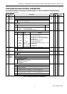
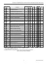
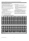
Control Point / Setpoint Adjustment CPATYP
(C.05)
The control point or setpoint can be adjusted via the internal
or external potentiometer connected to the CPA/SPA input.
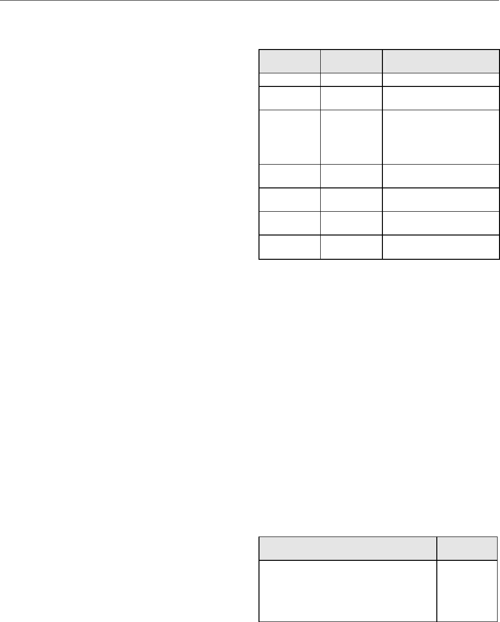
The potentiometer type is selected by the configuration
parameter CPATYP (see Table 6).
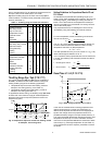
Table 6. Selection of CPA/SPA Type
CPATYP
CPA / SPA
range
sensor /
remote setpoint unit type
CPATYP 0
CPA: ±5 K
internal
CPATYP 1
(953...1053Ω)
CPA: ±5 K
T7412B1016 (Pt 1000)
CPATYP 2
(100kΩ...0Ω)
CPA: ±5 K
T7412B1057 (Pt 1000)
T7412C1030 (Pt 1000)
T7412B1008 (NTC 20kΩ)
T7412C1006 (NTC 20kΩ)
43193982-001
CPATYP 3
(10...20kΩ)
SPA:
15 ... 30°C
T7412B1024 (BALCO 500)
T7412B1040 (Pt 1000)
CPATYP 4
(0...10kΩ)
CPA: ±5 K
HCW 23 (setpoint wheel
printed with +/- 5 K)
CPATYP 5
(0...100kΩ)
SPA:
15...30°C
43193982-001
CPATYP 6
(0...100kΩ)
SPA: 0...50°C
or 0...130°C
43193982-001
Output Control Range Selection
YRange (C.06)
The configuration parameter YRange is available only on the
R7426C controller and is required to select the output control
range (0...100%) to either 2...10 Vdc (YRange = 0) or
0...10 Vdc (YRange = 1). The selected control range is
common to all outputs.
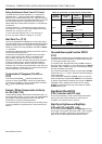
Enabling the Start-up Routine (C.07)
A start-up routine is provided to prevent start-up problems for
the R7426B,C controllers (three outputs). This routine can be
enabled by setting the configuration parameter Startup to
ON.
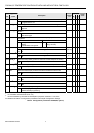
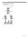
Individual Output Function Selection
YxMode, x = 1, 2, or 3 (C.08...C.10)
The R7426A,B controllers provide a choice of output signals
suitable for operating a range of final control devices
according to the configuration parameter Y1Mode (for
R7426A,B) and Y2Mode, Y3Mode (for R7426B, only).
Each output can be configured individually by this con-
figuration parameter (see Table 7).
Table 7. Individual Output Function Selection
output function
YxMode
(x = 1, 2 or 3)
Valve or damper actuators (floating mode) 0
2-stage ON/OFF Sequence Control 1
3-stage Binary ON/OFF Sequence Control 2
Electric Heat Current Valve (pwm output) 3
unconfigured 4