


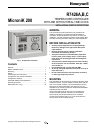
R7426A,B,C TEMPERATURE CONTROLLER WITH AND WITHOUT REAL-TIME CLOCK
EN1B-0203GE51 R0507C 2
WIRING
Screwless type, spring loaded terminals are provided on
the controllers for panel and field wiring. These terminals
are suitable for solid conductors as well as tinned or with
multicore cable end, stranded wires up to 1.5 mm
2
. To
make a termination, push the wire into the terminal or insert
a small screwdriver from the front of the controller into the
spring-release hole and insert the wire. Check for proper
connection by short pull on the wire.
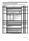
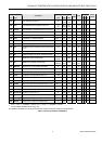
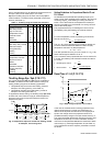
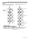
Table 1.
Terminal Connection
controller to CPA/SPA potentiometer
R7426A,B,C T7412B1016
T7412B1057/1008
T7412C1030/1006
T7412B1024
T7412B1040
terminal 2 terminal 4 terminal 4 terminal 4
terminal 4 terminal 5 terminal 6
terminal 5+6
R7426A,B,C 43193982-001 - -
terminal 2 terminal 1 - -
terminal 4 terminal 3 - -
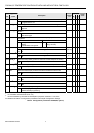
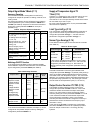
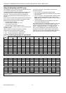
Table 2. Wire Dimensions
length max.
wiring run
type of
wires
1.0 mm
2
1.5 mm
2
from controller to all
input and output
devices
local
standard
100 m 150 m
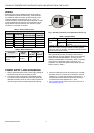
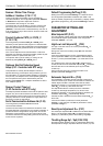
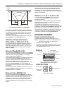
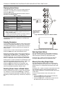
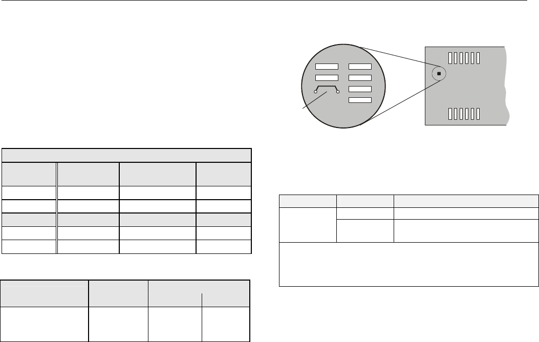
W303
Fig. 2. Parallel Connection of Compensation Sensor T3
Table 3. Jumper States
jumper
1)
state description
closed T3 supplied by this controller
W303
open
T3 supplied from another
controller
1)
Default jumper position = closed. Cut (open) jumper W303
only if the T3 input is fed from another controller (parallel
connection, max. six devices). This disconnects the T3 input
from the internal power supply
Wiring should be done only according to the actual job
wiring diagrams or wiring diagrams shown in the mounting
instruction sheet EN1B-0202GE51. The wiring to the
CPA/SPA potentiometers is described in Table 1. All wiring
must conform to applicable codes, ordinances, and
regulations. The maximum allowed wiring length per wire
size are shown in Table 2.
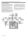
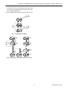
POWER SUPPLY AND GROUNDING
1. Refer to job drawings and verify correct supply voltage to
transformer (230 Vac) and controller (24 Vac).
2. Connect line power conductors to transformer primary.
Line power must be supplied from a breaker panel with
dedicated controller circuit. Do not turn the line power on
until all wiring has been checked against job drawings.
3. Connect transformers 24 Vac secondary to the controller
terminals 18 and 19. Connect one conductor to terminal
marked 24 V∼ and the other to terminal marked 24 V⊥. If
controllers are interconnected all terminals 19 must be
connected to the same potential 24 V⊥ level.
4. Do not connect the secondary side of the transformer to
the installation ground.