


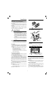
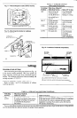
MOUNTING THE THERMOSTAT
1. Remove the thermostat cover by pulling the bottom
edge of the cover outward away from the base until it snaps
free from the cover clip.
NOTE: The cover is hinged at the top and is removed by
pulling out at the bottom.
2. Carefully remove and discard the polystyrene packing
insert that protects the mercury switches during shipment.
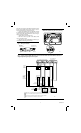
3. Turn over the thermostat base and note the spring
fingers that engage the subbase contacts. Make sure the
spring fingers are not bent flat, preventing proper electri-
cal contact with the subbase.
4. Set the heat anticipator indicator(s) to 0.1A for
proper system operation (Fig. 11).
5. Note the two tabs on the top inside edge of the
thermostat base. The tabs fit into the corresponding slots
on the top of the subbase. Mount the thermostat on the
subbase. See Fig. 12.
6. Align the two captive mounting screws in the thermo-
stat base with the posts on the subbase (Fig. 12). Tighten
both screws. Do not overtighten the screws or damage to
the subbase posts can result.
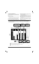
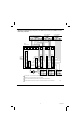
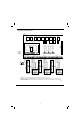
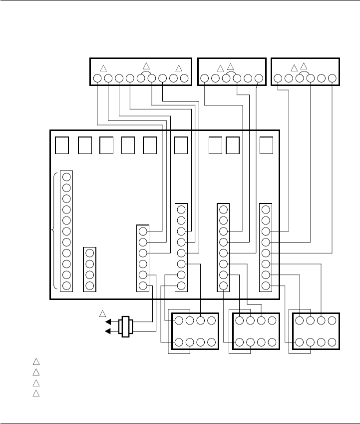
Fig. 7—Typical hookup for MABS II and MABS II-L Control Panels with T874A Thermostat/Q674B,D
Subbases in single-stage heating-cooling zone system. MABS II Control Panel shown; MABS II-L Control
Panel hookup is the same.
4
M1634
Y
2
1 POWER SUPPLY. PROVIDE DISCONNECT MEANS AND OVERLOAD PROTECTION AS REQUIRED.
JUMPER RC, RH TOGETHER AND WIRE AS SINGLE R TERMINAL.
ZONE 1 O AND B TERMINALS MUST BE CONNECTED FOR PROPER SYSTEM OPERATION.
DO NOT CONNECT W2 AND Y2 TERMINALS TO CONTROL PANEL.
Y
1
O
G
2
G
1
R
C
R
H
B
W
2
W
1
E
ADD-A-
ZONE
EM. HEAT
RELAY
SECOND
STAGE
RELAY
FAN
RELAY
HEAT
RELAY
COOL
RELAY
CAC
RELAY
ZONE 1
RELAY
ZONE 2
RELAY
ZONE 3
RELAY
A
4
A
3
A
2
A
1
T
8
T
7
T
6
T
5
T
4
M
6
M
4
M
1
ZONE 3
T
8
T
7
T
6
T
5
T
4
M
6
M
4
M
1
ZONE 2
T
8
T
7
T
6
T
5
T
4
M
6
M
4
M
1
ZONE 1
O
1
G
1
B
1
E
1
2
1
CHANGEOVER
CONTROL
COOL
FAN
HEAT
EM. HEAT
24 V, 40 VA
TRANSFORMER
456Z
DAMPER
ACTUATOR
123X
456Z
DAMPER
ACTUATOR
12
3
X
456Z
DAMPER
ACTUATOR
123X
L1
(HOT)
L2
1
MABS II
CONTROL PANEL
Y1 Y2 RC RH W2 W1
2
T874A THERMOSTAT/
Q674D SUBBASE
Y1 Y2 RC RH W2 W1
2
T874A THERMOSTAT/
Q674D SUBBASE
Y1 RC RH W1 W2 Y2
2
T874A THERMOSTAT/Q674B SUBBASE
OGB
TO SINGLE-
STAGE
HEATING/
COOLING
EQUIPMENT
3 4 4
2
4
3
4