


3 69-0580—2
letter code is located near each subbase terminal for identi-
fication. The terminal barrier permits straight or conven-
tional wraparound wiring connection (Fig. 4).
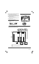
2. Some Q674 Subbases have RC and RH terminals
for isolated heating and cooling transformers. For zoning
systems, jumper RC and RH terminals as shown in Fig. 5
and wire as single R terminal.
3. Firmly tighten each terminal screw.
4. Fit wires as close as possible to the subbase. Push
excess wire back into hole.
5. Plug the hole with nonflammable insulation to pre-
vent drafts from affecting the thermostat.
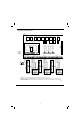
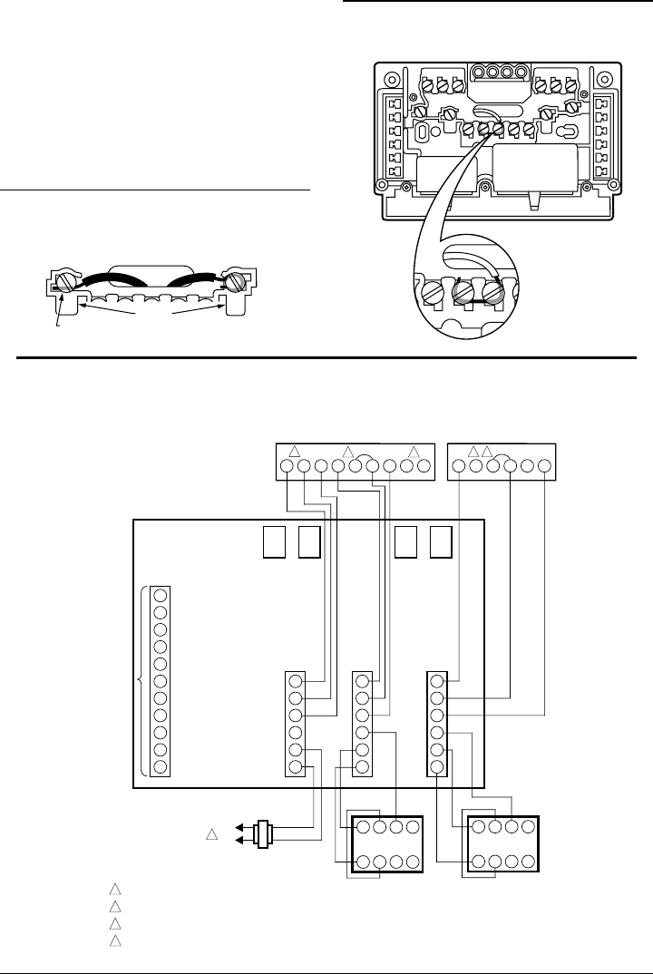
Fig. 5—Jumper RC and RH terminals for single
transformer system. Strip wire 3/4 in. [19 mm].
R
C
R
H
R
C
R
H
M929
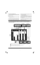
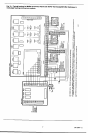
Fig. 6—Typical hookup for MM-2 Mini-zone Control Panel with T874A Thermostat/Q674B,D Subbase in
single-stage heating-cooling two-zone system.
POWER SUPPLY. PROVIDE DISCONNECT MEANS AND OVERLOAD PROTECTION AS REQUIRED.
ZONE 1 O AND B TERMINALS MUST BE CONNECTED FOR PROPER SYSTEM OPERATION.
JUMPER RC AND RH TERMINALS TOGETHER AND WIRE AS SINGLE R TERMINAL.
DO NOT CONNECT W2 AND Y2 TERMINALS TO CONTROL PANEL.
1
1
M1633
HEAT
RELAY
COOL
RELAY
ZONE 1
RELAY
ZONE 2
RELAY
Y2
Y1
O
G2
G1
RC
RH
B
W2
W1
E
T6
T5
T4
M6
M4
M1
T6
T5
T4
M6
M4
M1
O1
G1
B1
B
2
1
CHANGEOVER
CONTROL
COOL
FAN
HEAT
24 V, 40 VA
TRANSFORMER
MINIZONE
(MM-2)
CONTROL
PANEL
4 56Z
DAMPER
ACTUATOR
123X
4 56Z
DAMPER
ACTUATOR
123X
L2
L1
(HOT)
2
ZONE 2ZONE 1
3
4
OG B
Y1
RC RH W1
4
T874A THERMOSTAT/Q674B SUBBASE
2
Y1 Y2
RC
RH W2
4
T874A THERMOSTAT/
Q674D SUBBASE
3
TO SINGLE-
STAGE
HEATING/
COOLING
EQUIPMENT
W2
Y2
W1
3
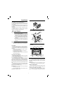
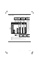
Fig. 4—Wiring connections.
FOR STRAIGHT
INSERTION–
STRIP 5/16 in. [8 mm]
FOR WRAPAROUND–
STRIP 7/16 in. [11 mm]
SUBBASE TERMINAL SCREW
M928
BARRIER