


Installation
WHEN INSTALLING THIS PRODUCT…
1. Read these instructions carefully. Failure to fol-
low them could damage the product or cause a hazard-
ous condition.
2. Check the ratings given in the instructions and on
the product to make sure the product is suitable for your
application.
3. Installer must be a trained, experienced service
technician.
4. After installation is complete, check out product
operation as provided in these instructions.
CAUTION
1. Disconnect power supply to prevent electrical
shock or equipment damage.
2. To prevent interference with the thermostat
linkage, keep wire length to a minimum and
run wires as close as possible to the subbase.
3. Do not overtighten thermostat captive mount-
ing screws, because damage to subbase threads
can result.
4. Do not short across terminals of systems con-
trols. This can burn out the thermostat heat
anticipator.
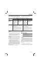
IMPORTANT: Thermostats are calibrated at the factory by
using subbases mounted at true level. Inaccurate sub-
base leveling will cause thermostat control deviation.
LOCATION
Locate the subbase about 5 ft [1.5 m] above the floor in
an area with good air circulation at average temperature.
Do not mount the subbase where the thermostat may be
affected by:
—drafts or dead spots behind doors and in corners.
—hot or cold air from ducts.
—radiant heat from sun, appliances or fireplace.
—concealed pipes and chimneys.
—unheated (uncooled) areas such as an outside wall
behind the thermostat.
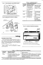
MOUNTING THE SUBBASE
The thermostat subbase can be mounted on a horizontal
outlet box or directly on the wall.
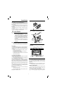
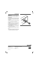
1. To mount on a horizontal outlet box, install the sub-
base on the outlet box as shown in Fig. 1.
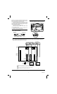
For a wall installation, hold the subbase in position and
mark holes for the anchors (Fig. 2). Obtain wall anchors
locally. Take care that the wires do not fall back into the
wall opening. Set aside subbase. Drill two 3/16 in. [4.8 mm]
holes and gently tap anchors into the holes until flush with the
wall.
2. Pull electrical wires through the cover plate (if used)
and subbase cable opening (Fig. 3). See Wiring the Sub-
base section before pulling any wires.
IMPORTANT: Use 18 gauge, color-coded thermostat
cable for proper wiring.
3. Secure the subbase with the screws provided. Do not
fully tighten the subbase screws.
2
Fig. 1—Installation of subbase on outlet box.
!
M3703
SUBBASE
HORIZONTAL
OUTLET
BOX
1
NOT INCLUDED WITH UNIT.
1
Fig. 2—Installation of subbase on wall.
WIRES THROUGH
WALL OPENING
WALL
WALL
ANCHORS
(2)
SUBBASE
MOUNTING
SCREWS (2)
M926
MOUNTING
HOLES
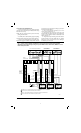
Fig. 3—Subbase components and leveling
procedure.
SPIRIT LEVEL
MOUNTING
HOLES (2)
M927
TOP
MOUNTING
HOLES (2)
WIRING
TERMINAL
THERMOSTAT
CABLE OPENING
TO SPRING FINGER
CONTACTS ON THE
THERMOSTAT
(UP TO 12)
POST (2) FOR
MOUNTING
THERMOSTAT
4. Level the subbase using a spirit level, as shown in
Fig. 3, and firmly tighten the subbase mounting screws.
The subbase mounting holes allow minor out-of-level
adjustments.
IMPORTANT: An incorrectly leveled subbase will cause
the temperature control to deviate from set point.
WIRING THE SUBBASE
All wiring must comply with local electrical codes and
ordinances. Follow equipment manufacturer wiring in-
structions when available. To wire subbase:
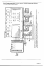
1. Connect wires to the subbase terminals. Refer to
Figs. 6-10 for wiring diagrams of typical zone systems. A