


PRO-2200 Two Reader Module PRO22R2 9Installation Guide
N-1000-IV FourN-1000-IV Four
N-1000-IV FourN-1000-IV Four
N-1000-IV Four
Reader BoardReader Board
Reader BoardReader Board
Reader Board
Description
The Two Reader Board provides support for up to two access control doors by providing
connections for Wiegand or Clock/Data type readers, supervised inputs and relay outputs.
This board can be rack mounted, in which case, only one edge is accessible for wiring.
Mounting the board flat increases the amount of available I/O slightly but also significantly
decreases the number of boards that can be mounted in one enclosure.
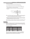
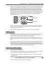
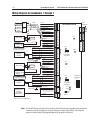
The I/O terminals are organized to support two doors. Starting at the bottom of the rack-
mount side of the board, the first connector provides power to the board. The next connec-
tor provides communication with the Intelligent Controller (PRO22IC). The next set of
terminals is used to connect reader 2. The next set of terminals is used to connect the I/O
typically associated with reader 2, namely the Door Status and REX status inputs and the
Door Lock and Lock Status relay outputs. Continuing up this edge the next two connec-
tors provide the reader and associated I/O terminals for reader 1. The last connector on
the rack-mount edge provides terminals for two additional general-purpose alarm inputs
When the board is mounted flat, two additional relay outputs and two additional general-
purpose alarm inputs are available along with two dedicated alarm inputs for cabinet
tamper and power fault detection on the opposite edge of the board.
The reader interface accepts a Wiegand signal of Data 1 and Data 0 or a Clock and Data
signal and provides 5 VDC or 12 VDC reader power, a tri-stated LED control and buzzer
control. Two of the six form-C relay outputs are sized for the inductive load of door locks
and the other four are designed to handle dry-circuit signals. All of the inputs are capable
of four-state supervision except the two dedicated inputs. Communication to the control
panel is accomplished via an RS-485 interface. This board requires 12 VDC input power.
When communication to the control panel is lost this board can grant access based on
facility code only. General purpose outputs will retain the setting at the time communica-
tion was lost. Up to eight facility codes may be active in each PRO22R2. Keypad input
must follow the reader input format and is in place of or multiplexed with the reader data.
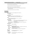
Set Up
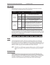
Jumper Settings:
Jumper Setting Default
Selected
J1
OFF
*
Port 1 RS-485 EOL terminator is not active
ON Port 1 RS-485 EOL terminator is active
J2
5 * Reader 1 Power Terminal provides 5 VDC
12 Reader 1 Power Terminal provides 12 VDC
J3
5 Reader 2 Power Terminal provides 5 VDC
12 Reader 2 Power Terminal provides 12 VDC
*