


14 PRO-2200 Two Reader Module PRO22R2Installation Guide
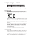
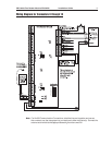
Relays 1 and 3 are rated for and normally used to control the door locks associated with
readers 1 and 2 respectively. While Relays 1 and 3 are sized to handle the typical loads
generated by electrical locks, load switching can cause abnormal contact wear and
premature contact failure. Switching of inductive loads (i.e., strike) also causes EMI
(electromagnetic interference) which may interfere with normal operation of other equip-
ment. To minimize premature contact failure and to increase system reliability, contact
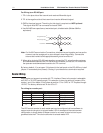
protection circuit is highly recommended. The following two circuits are suggested. Locate
the protection circuit as close to the load as possible (within 12 inches [30cm]), as the
effectiveness of the circuit will decrease as the distance from the load increases.
(See diagram to follow.)
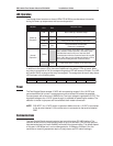
Relays 2 and 4 are dry-circuit level signal relays typically used to indicate the status of
the door lock. Relays 5 and 6 are general-purpose relay outputs and are not available
when the board is rack mounted.
Use sufficiently large gauge of wires for the load current to avoid voltage loss.
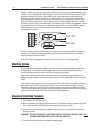
Mounting Options
This board can be mounted on-edge in the rack-mount enclosure provided by Northern
Computers or it can be mounted flat against any surface using standoffs under the
mounting holes provided in each of the four corners of this board.
When this board is rack-mounted, the connectors for two general-purpose inputs, two
general-purpose outputs, and two dedicated inputs are not accessible and should not be
used.
The most common reason for mounting a board flat is that it is being installed remotely to
be located near the door(s) being monitored. In this case it will be mounted in its own
enclosure creating the need to monitor cabinet tamper and power fault detection inputs.
The two additional general-purpose inputs and outputs provided allow for the monitoring of
extra alarm sensors and control of local horns or other equipment.
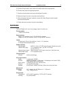
Suggested Installation Sequence
1. Set Jumpers and DIP switches.
2. Mount this board in the appropriate enclosure. If this board is being mounted in a rack,
the component side of the board is to the right when facing the rack.
3. Connect the communications and power supply to the circuit boards with the Power
Supply Harness.
WARNING: DO NOT CONNECT THE POWER SUPPLY TO THE AC SOCKET UNTIL ALL
WIRING HAS BEEN INSTALLED AND RECHECKED.
4. Connect wiring to the reader interfaces as appropriate.