


16 PRO-2200 Two Reader Module PRO22R2Installation Guide
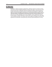
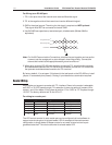
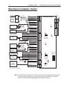
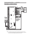
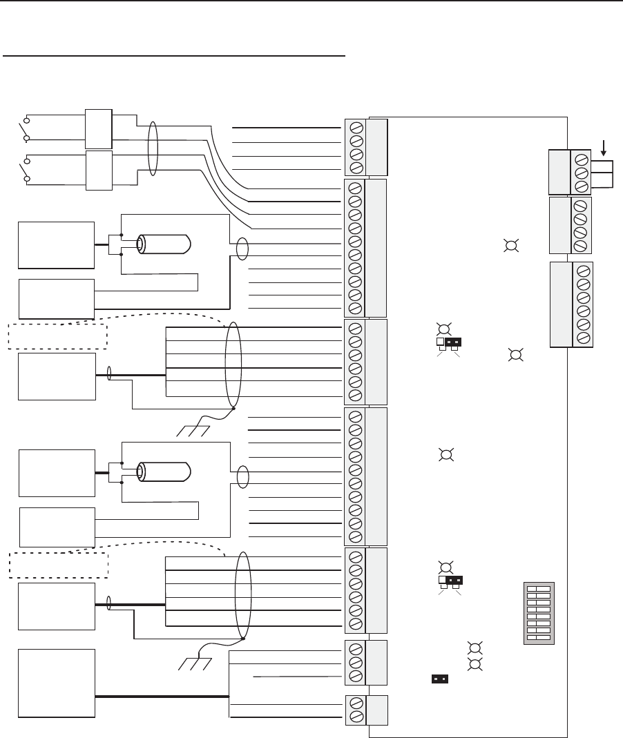
Wiring Diagram for Connectors 1 through 7
Note: For N-485 Communication Connections, twist the blue pair together and use as the
common; use the orange pair as your data pair, observing polarity. Connect the
external drain shield to the appropriate earth ground on one end.
1
2
3
4
1
2
Two Reader Board
Reader 1
Reader 2
Input 5 Common
Input 5
RED
BLACK
Door
Status Switch
Relay 1 C
GREEN Input 6 Common
Egress
Push-Button
Switch
WHITE Input 6
Input 1
Input 1 Common
Input 2
Relay 1 NO
S-4
Suppressor
Door Lock
BLACK
RED
DRAIN
RED +5 or +12V DC Out
YELLOW Beeper
BROWN Red LED
BLACK Common
GREEN Data-0
NC
KP-13
Weigand
Keypad
Separate
Power
Supply
-
VDC
+
Input 2 Common
Relay 1 NC
Relay 2 NO
Relay 2 C
Relay 2 NC
1
2
3
4
5
6
10
1
2
3
4
5
6
7
8
9
WHITE Data-1
Chassis GND
Inside Panel
1
2
3
4
5
6
10
1
2
3
4
5
6
7
8
9
Input 3
Input 3 Common
Input 4
Input 4 Common
Relay 3 C
Relay 3 NO
Relay 3 NC
Relay 4 NO
Relay 4 C
Relay 4 NC
DRAIN
RED +5 or +12V DC Out
YELLOW Beeper
BROWN Red LED
BLACK Common
GREEN Data-0
Proximity
Reader
WHITE Data-1
Chassis GND
Inside Panel
Voltage Is Selected By
Jumper J2 On Board
S-4
Suppressor
Door Lock
BLACK
RED
Separate
Power
Supply
–
VDC
+
EOL
EOL
1
2
3
485-Com +
485-Com -
485-Gnd
CardRack
PWR & Com
Harness*
( For Rack
Mount Only )
RS-485 Power
D73
D75
D74
J1 - RS485
Termination
Jumper
D79
D80
1
2
3
4
5
6
7
8
S1
1
2
3
4
5
6
1
2
3
1
2
3
4
D77
D78
12V 5V
12V 5V
Configuration
Dip Switches
J3 - Reader2
VDC Select
J2 - Reader1
VDC Select
Voltage Is Selected By
Jumper J3 On Board
PWR +
PWR -
Typical Connection
Short
Together*
*Rack mount configuration