


PRO-2200 Two Reader Module PRO22R2 15Installation Guide
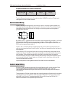
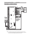
5. Connect wiring to alarm input sensors or install jumper wire as appropriate.
6. Connect relay output wiring as appropriate.
7. Connect communications wiring to the Intelligent Controller.
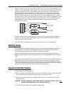
8. Recheck wiring for correct connections and continuity.
9. When all boards have been installed, connect the Power Supply Cord for proper
connections and power.
10. Setup the panel controls using the host software.
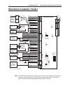
Specification
The Two Reader is for use in low voltage, class 2 circuits only.
Primary power:
12VDC±10% 400mA
Relay contacts:
Relays 1 & 3 outputs, Form-C, 5A @ 28 VDC, resistive
Relays 2 & 4 & 5 & 6 outputs, Form-C, 2A @ 28 VDC, resistive
Inputs:
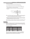
8 supervised, End of Line resistors 1k ohm ± 1% tolerance
2 unsupervised dedicated inputs
Reader interface
Reader power 5 VDC (5 - 6.2) or 12 VDC (pass-through) 150mA max. each
Reader LED output TTL compatible, high > 3V, low < 0.5V, 5mA
source/sink max.
Reader buzzer output Open collector, 5 VDC open circuit max. 10mA sink max.
Reader data inputs TTL compatible inputs
Communication:
RS-485 9,600 to 38,400 bps
Wire requirements:
Power 1 twisted pair, 18AWG
RS-485: 24AWG, 4,000 feet (1,200m) max., 2-twisted pair with shield (120Ω,
23pf) (Belden 9842 or equivalent.)
Alarm inputs 1 twisted pair per input, 30 ohms max.
Outputs As required for the load
Readers 6 conductors, 18AWG, 500 feet (150m) max. shield and drain
Mechanical:
Dimension 5.5" (140mm) W x 9" (229mm) L x 1" (25mm) H
Weight 12 oz. (340g) nominal
Environment:
Temperature 0°C to +49°C, operating, –55°C to +85°C, storage
Humidity 0% to 85% RHNC