


48 MS-9600LS Series Manual — P/N 52646:B2 2/12/2010
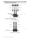
Installation Notification Appliance Circuits
The following sections describe the configuration and wiring of Style Y and Style Z Notification
Appliance Circuits on the FACP main circuit board. The NACs are configured for Style Y (Class
B) from the factory. Refer to “Configuring NACs” on page 48 for information on changing the
NAC configuration to Style Z (Class A) and preparing the NACKEY configuration card located in
JP8, when installing a 4XTMF Transmitter Module.
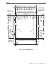
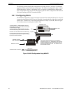
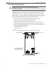
2.4.1 Configuring NACs
The Notification Appliance Circuits on the main circuit board are configured for Style Y or Style Z
by properly orienting the NACKEY card in JP8 which is located at the top of the main circuit board
near the NAC Terminal TB4. The default configuration is for Style Y (Class B). Refer to Figure
2.6 for information on installing the NACKEY card.
J10
J11
4XTMF OPT BD
JP8
CLASS A
CLASS B
NACKEY -PCA
NACKEY -PCA
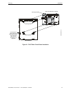
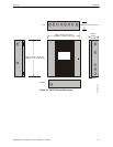
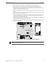
Figure 2.6 NAC Configuration Using NACKEY
NACKEY Card
JP8
Top edge of FACP
Main Circuit Board
• Style Z (Class A) - install NACKEY into JP8
with Class A pointing down toward circuit board
as illustrated to the right.
• Style Y (Class B) - install NACKEY into JP8
with Class B pointing down toward circuit board .
NACKEY must be inserted with text side facing
in toward center of main circuit board and key
into key-slot as illustrated to the right. It is keyed
to prevent incorrect insertion.
TB4
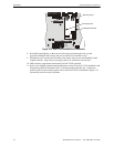
If the 4XTMF Option Module is to be installed in
connectors J10 and J11, the NACKEY card must be
carefully separated at the scored mark and only the
required half installed into JP8. This will allow room
for the 4XTMF module.
scored mark
4XTMF Module connectors
NACKEY card slot
Key
Key-slot
connectors for 4XTMF option module