


MS-9600LS Series Manual — P/N 52646:B2 2/12/2010 153
Alarm Operation Operating Instructions
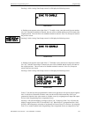
INV ID - indicating that an incorrect device code (Type ID) has been programmed for an
installed device (for example, Photo has been programmed but an Ion detector has been
installed)
SW TBL - indicating a module has failed the testing of its Class A switching relay
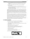
• Fourth line in display:
– Time; the current time in this example is 10:00A which represents 10:00 AM
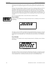
– Date; the current month, day and year in this example is 01 for January, 08 for the 8th day of
the month, and 10 for the year 2010
– Device Address; 1D001 in this example 1 represents SLC Loop1, D represents a detector,
and 001 represents device address 001
Pressing the Acknowledge/Step or Alarm Silence key will cause the pulsing piezo to silence and the
system Trouble LED to change from flashing to on steady. This block acknowledgment occurs
regardless of the number of troubles, alarms and supervisory events active in the system. When the
Acknowledge/Step key is pressed and at least one new alarm or trouble exists in the system, the
‘acknowledge’ message is sent to the printer and history file. If the trouble clears, either before or
after the Acknowledge/Step key is pressed, the ‘clear trouble’ message is sent to the printer and his-
tory file.
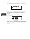
If all troubles clear and there are no supervisory or fire conditions active in the system, the system
returns to normal mode operation and the System All Normal message is shown on the LCD display
and sent to the history and printer files. The auto-restore feature will restore cleared troubles even
if the troubles were never acknowledged. Note that pressing the Alarm Silence key when only trou-
bles exist in the system will have the same effect as pressing the Acknowledge/Step key.
If multiple trouble conditions exist in the system, they will be automatically scrolled on the LCD
display at a three second rate. If a combination of alarms, troubles and/or supervisory conditions
simultaneously occur in the system, only the alarms are scrolled on the display.
4.5 Alarm Operation
Alarm operation is similar to trouble operation with the following differences:
• The piezo sounder produces a steady output as opposed to a pulsed output
• The Fire Alarm LED flashes 1 second On and 1 second Off
• The LCD displays Alarm along with the device name, type, address, adjective/noun, associated
zones and time/date
• Alarms latch and are not allowed to clear automatically
• Alarms activate software zones if so programmed
• Timers for Silence Inhibit, Autosilence and Trouble Reminder are started
• Alarms activate the general alarm relay and general alarm zone Z00
• The trouble relay is not activated
• Store event in history buffer
• Terminate upload or download communications
• Alarms must be Acknowledged before the FACP can be reset
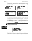
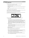
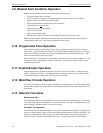
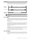
A typical alarm display would be as illustrated below:
ALARM PULL STATION
<ADJ> <NOUN>
Z000
10:00A 010810 1M001