


196 MS-9600LS Series Manual — P/N 52646:B2 2/12/2010
Appendix E: Wire Requirements
T-tapping of the SLC loop wiring is allowed for 2-wire (Style 4) configurations. The total
resistance of any branch cannot exceed 40 ohms. The total wire length of all branches cannot
exceed 10,000 feet (3,000 m).
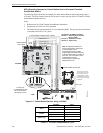
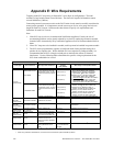
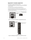
Connecting external system accessories to the FACP main circuits must be carefully considered to
ensure proper operation. It is important to use the correct type of wire, wire gauge and wire run
length for each FACP circuit. Reference the chart below to specify wire requirements and
limitations for each FACP circuit.
Note:
1. If the SLC loop is to be run in conduit with Notification Appliance Circuits, the risk of
encountering problems can be greatly reduced by exclusively employing electronic sounders
instead of more electronically noisy notification appliances such as electromechanical bells or
horns.
2. If two SLC loops are to be installed in conduit, each loop must be installed in separate conduit.
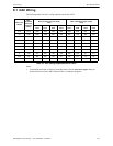
3. The SLC can be programmed to operate in LiteSpeed mode (factory default setting) for a
quicker device response time. While shielded wire is not required in LiteSpeed mode, it is
recommended that all SLC wiring be twisted-pair to minimize the effects of electrical
interference. Use the following table to determine the specific wiring requirements for the
SLC when unshielded wire is used:
CIRCUIT CONNECTIONS WIRE REQUIREMENTS
Circuit Type Circuit Function Wire Type and Limitations
Recommended Max.
Distance
Feet (meters)
Wire Gauge and Compatible Brands
SLC loop
(power-limited)
Connects to
Addressable Devices
CLIP MODE
Twisted, shielded pair
40 ohms maximum per length
of Style 6 and 7 loops. 40 ohms
per branch maximum for Style 4
loops
10,000 (3,000 m)
8,000 (2,400 m)
4,875 (1,450 m)
3,225 (980 m)
12 AWG (3.25 mm
2
): Genesis 4410,
Signal 98230, Belden 9583, WPW999
14 AWG (2.00 mm
2
):Genesis 4408 & 4608
Signal 98430, Belden 9581, WPW995
16 AWG (1.30 mm
2
): Genesis 4406 & 4606
Signal 98630, Belden 9575, WPW991
Direct Burial Cable
Isotec NP713110VNQ-S
18 AWG (0.75 mm
2
): Genesis 4402 & 4602
Signal 98300, Belden 9574, WPW975
Direct Burial Cable
Isotec NP714110VNQ-S
LITESPEED MODE
Twisted, unshielded pair
40 ohms maximum per length
of Style 6 and 7 loops. 40 ohms
per branch maximum for Style 4
loops
10,000 (3,000 m)
8,000 (2,400 m)
4,875 (1,450 m)
3,225 (980 m)
12 AWG (3.25 mm
2
): Belden 5020UL &
6020UL, Genesis WG-4315 & WG-4515
14 AWG (2.00 mm
2
):Belden 5120UL &
6120UL, Genesis WG-4313 & WG-4513
16 AWG (1.30 mm
2
): Belden 5220UL &
6220UL, Genesis WG-4311 & WG-4511
18 AWG (0.75 mm
2
): Belden 5320UL &
6320UL, Genesis WG-4306 & WG-4506
Untwisted, unshielded pair
1
3,000 (900 m) 12-18 AWG (3.25 - 0.75 mm
2
) using listed wire
ACS-BUS
(EIA-485)
(power-limited)
Connects to
annunciator modules
Twisted pair with characteristic
impedance of 120 ohms
6,000 (1,800 m) 12 AWG (3.25 mm
2
)
ANN-BUS
(EIA-485)
(Power-limited)
Connects to
annunciator modules
Twisted pair 6,000 (1,800 m) Refer to “ANN-BUS Wiring” on page 23 for wire
requirements.
EIA-232
(power-limited)
connects to remote
PC computer
Twisted, shielded pair 50 (15 m) 18 AWG (0.75 mm
2
) minimum
MMF-300 and
MMF-301
(power-limited)
Initiating Device
Circuit
Maximum loop wire resistance
is 40 ohms for the MMF-300
and 20 ohms for the MMF-301
2,500 (760 m) 12-18 AWG (3.25 - 0.75 mm
2
)
MMF-302
(power-limited)
Initiating Device
Circuit
No more than a 2.4 volt drop
allowed at end of circuit.
Maximum loop wire resistance
is 25 ohms
2,500 (760 m) 12-18 AWG (3.25 - 0.75 mm
2
)
CMF-300
(power-limited)
Notification Appliance
Circuit
In alarm, no more than a 1.2
volt drop allowed at end of
circuit
Distance limitation set
by 1.2 volt maximum
line drop
12-18 AWG (3.25 - 0.75 mm
2
)
Table E.1 FACP Wire Specifications
1 When using untwisted, unshielded wire, full conduit is recommended for optimum EMI/RFI protection.