


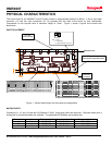
HMR4007
SENSOR PRODUCTS
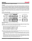
The second function, "CurrentPosition", is used to query the current position of the magnet. The following 16-bit
integer values are returned:
0-1024 normal position response where 1024 represents full scale response.
-1, -2 communications failure. The sensor failed to respond to the PC quickly enough. This is
usually caused by improper wiring, improper power settings, a timeout value too small for
the PC speed, or the DLL not being initialized before attempting to get the position.
-3 position error. The sensor communicated correctly, but the sensor card was not able to
calculate a valid position. A position error is usually caused by the magnet being off the end
of the board or not present.
The functions "SetAxialMode" and "SetRadialMode" are used to configure the sensor to use magnets in either the
axial mode or radial (see the introduction for a description of axial and radial modes). The sensor is shipped with the
axial mode selected. Once set into an operating mode, that mode is retained in nonvolatile RAM.
The functions "EnableDAC" and "DisableDAC" are used to enable and disable the digital to analog (DAC) output on
port J2. The sensor is shipped with the DAC enabled. Once set into an operating mode, that mode is retained in
nonvolatile RAM.
HMR4007.exe: This is a simple Visual Basic 5.0 executable that demonstrates the use of the DLL and shows a
simple graphical display of the current position. Source code for the program is available and can be modified as
desired. The position window will turn yellow in the event of a communications failure, or turn red in the event of a
position error.
MAGNET CONSIDERATIONS
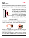
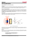
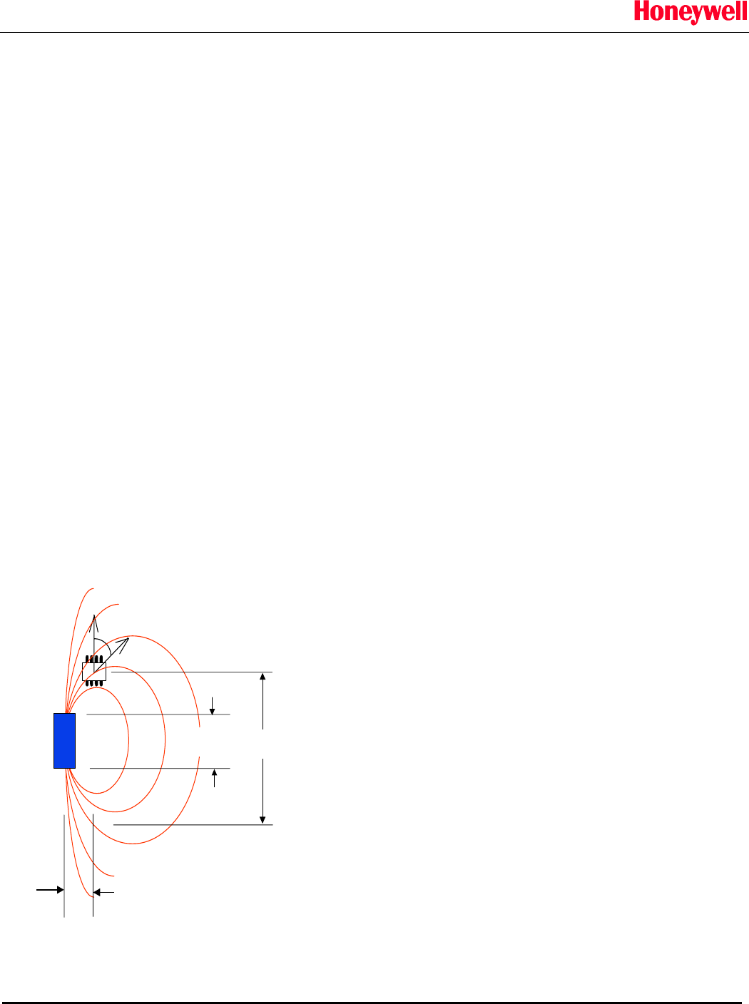
The choice of magnet to be used with the HMR4007 is critical to its accuracy. Because a magnet's field extends
beyond the boundaries of the material, a magnet has two dimensions to consider: its physical (material) length and its
apparent (magnetic) length. The heart of the HMR4007 is Honeywell's HMR1501 magnetoresistive (MR) sensor that
responds to the angle between the chips' sensitive axis and the magnetic field. The HMR1501 has a maximum
response when this angle is +/-45 degrees. We can, therefore, define the magnet's apparent length as the distance
between the +45 and -45 degree points at the gap distance.
As the gap between the magnet and the sensor array increases, the
apparent length of the magnet increases as well. A general rule of
thumb for a cylindrical bar magnet is that the apparent length will
increase by the amount of the gap. A twenty-five millimeter long
magnet for example will appear to be thirty-five millimeters long at a
gap of 10 millimeters. Since magnetic fields are highly nonlinear and
subject to the exact geometry and properties of the material, this is only
a general guide.
= f(4)
HMR1501
response
4
B
B
x
N
S
gap
physical
length
apparent
length
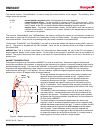
The HMR4007 uses three sensors in its array at all times in order to
calculate position. It automatically selects the sensors closest to the
magnet for this purpose. The apparent magnet length must, therefore
be greater than he spacing between three sensors, and this distance is
23.2mm for the HMR4007.
The disadvantage of increasing the gap between the sensor and
magnet in order to increase its apparent length is that a magnet's field
strength decreases exponentially with gap. In order to maintain the MR
sensor's response the magnetic field at the sensor must be greater
than 35 gauss. Unless extremely strong rare earth magnets are
economically feasible or a large gap is required because of restrictions
on where the magnet and array can be mounted, it is usually better to
keep the gap to a minimum and use a longer magnet.
Figure 3. Magnet apparent length
900301 01-03 Rev. A
Solid State Electronics Center
• www.magneticsensors.com • (800) 323-8295 • Page 8