


HMR4007
SENSOR PRODUCTS
PHYSICAL CHARACTERISTICS
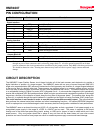
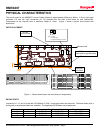
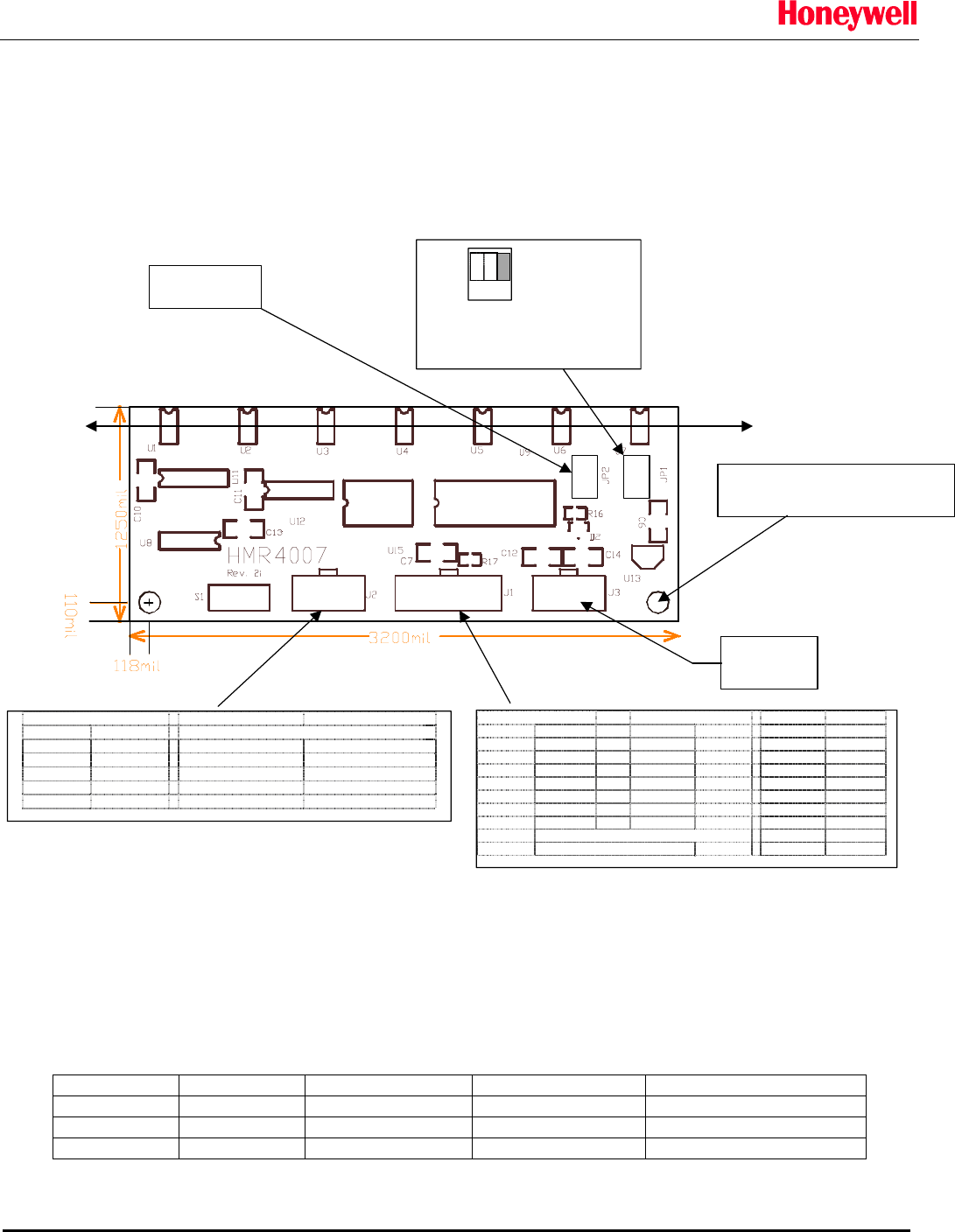
The circuit board for the HMR4007 Linear Position Sensor is approximately 340mm by 80mm. A 6-pin right angle
connector (J1) and two 4-pin connectors (J2, J3) protrude from the back of the board for user connections.
Components on the top-side have a maximum height of 12mm. Figure 1 shows a typical circuit board with
dimensions.
PARTS PLACEMENT
4 5 6
1 2 3
4 5 6
1 2 3
6 5 4 3 2 14 3 2 1
PC(parallel port) Sensor Board
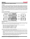
LPT bit LPTpin J1 pin uPbit function color
S3 15
<
1RA3Tx_CLK(gray)
S4 13
<
2 RA2 Tx (ye llow )
D1 3
>
3RA1 Rx(blue)
D0 2
>
4RA0Rx_CLK(white)
--
<>
5Vcc+5-28 VDC(red)
-19
<>
6 GND power gnd (black)
Sx = status (LPT port base address + 1, Bit x)
Dx = data
(
LPT
p
ort base address + 0
,
Bit x
)
Sensor Board
J2 pin uP pin function
1 Vcc power input (5-28VDC)
2 RA4 status (TTL output) Lo
g
ic 0 = out
p
ut not valid
Logic 1 = output valid
3 D/A Output analo
g
out
p
ut
(
0 - 2.25V
)
4 GND power ground
xx
Not used
leave all OPEN
4-40NF mounting holes
(connected to ground plane)
USB port
not used
Sensed axis
x
xxx
1
2
3
JP1
Where 1 = J3 (USB)
2 = J2 (Analog output)
3 = J1 (digital communications) - shown above
Figure 1 – Sensor board layout and connector pin designations
MATING PARTS
Connectors J1, J2, and J3 mate with GC/Waldom C-Grid crimp-style shells and terminals. Polarized shells (with a
locking tab) or unpolarized shells are available. The applicable GC/Waldom part numbers are:
Connector pins Polarized shell Unpolarized shell Crimp terminals
J1 6 50-57-9406 50-57-9006 16-02-0097
J2 4 50-57-9404 50-57-9004 16-02-0097
J3 4 50-57-9404 50-57-9004 16-02-0097
Solid State Electronics Center
• www.magneticsensors.com • (800) 323-8295 • Page 5