


HMR4007
SENSOR PRODUCTS
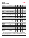
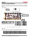
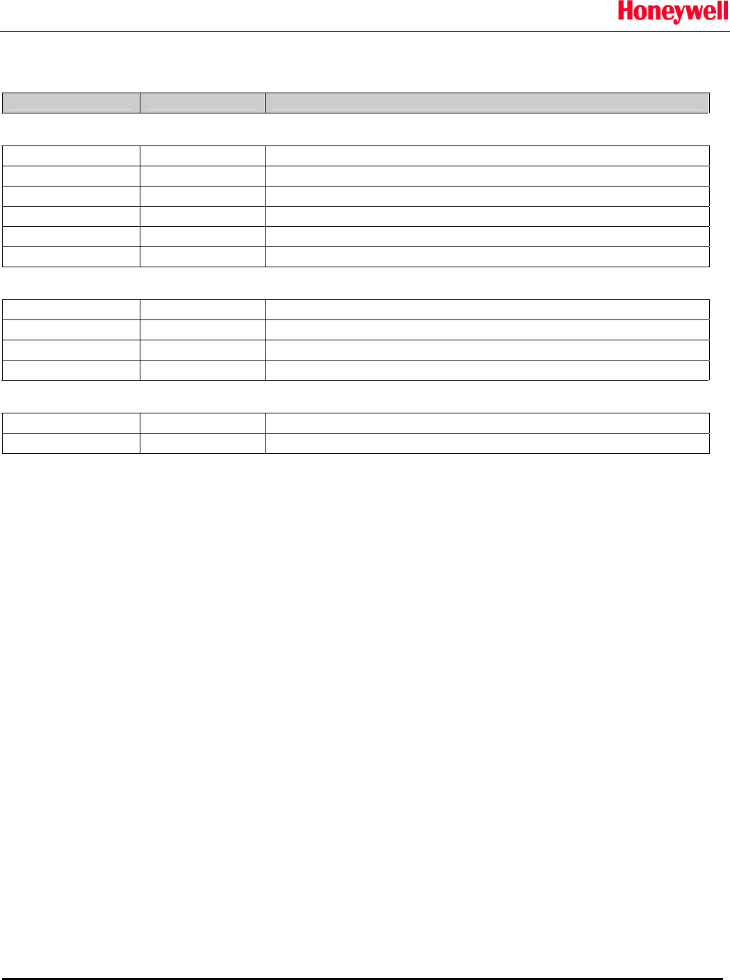
PIN CONFIGURATION
Pin Number Pin Name Description
Digital Interface
1 RTS Serial Clock Output
2 Data_Out Serial Data Output
3 Data_In Serial Data Input
4 CTS Serial Clock Input
5 Power Unregulated Power Input (+6 to +28 VDC) (see note 1)
6 GND Power and Signal Ground
Analog Interface
1 Power Unregulated Power Input (+6 to +28 VDC) (see note 2)
2 Analog Out 0 - 2.5 VDC analog output
3 Position Valid TTL level (0 = position invalid, 1 = position valid)
4 GND Power and Signal Ground
Jumper Block #1
2-5 Note 1 Analog Output port selected as power source
3-6 Note 1 Serial Communications port selected as power source
Note 1: The board contains three interface connectors for digital and/or analog communications. Power is supplied to the board
through any one of these connectors and is selected by jumper block #1. All of the ground connections on all three
ports are common to the circuit ground and are not affected by the jumper position. Only ONE of the three positions on
JP1 should be shorted at a time. Shorting more than one may result in excessive power supply currents and board
damage.
CIRCUIT DESCRIPTION
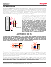
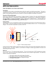
The HMR4007 Linear Position Sensor circuit board includes all of the basic sensors and electronics to provide a
digital indication of position of a target magnet. The HMR4007 starts with an array of seven Honeywell HMC1501
single axis magnetoresistive (MR) sensors to determine the field geometry and direction of a target magnet attached
to the moving part of a device under test. These sensors are supplied power by a constant voltage source, and the
use of an array of sensors helps to maintain accuracy over temperature and run-out. The sensor outputs are routed
to a multiplexed Analog to Digital Converter (ADC) integrated circuit. A microcontroller integrated circuit periodically
queries the multiplexed ADC and performs sensor offset and gain corrections and computes the position of the target
magnet as a function of the distance of travel along the long axis of the sensor board. The position data, along with
an error bit, is available thought the serial interface or is present on the Digital to Analog Converter (DAC) output port.
The serial interface is not needed in order to use the board’s stand-alone analog output. The microcontroller
also performs the external serial data interface and other housekeeping functions. An onboard EEPROM integrated
circuit is employed as a nonvolatile storage to retain necessary data and configuration variables for best performance.
The HMR4007 uses an on-board low drop out (LDO) +5 volt regulator so that a regulated +5 volt power supply or an
unregulated power supply in the range of +6VDC to +28VDC can be used. The power is supplied to the board
through one of the three user ports being (serial, analog, or USB) and a jumper is used to select which port is the
power source. Only one jumper should be in place at any one time as the board does not have over current
protection and use of more than one jumper can result in excessive power supply currents and board damage.
Solid State Electronics Center
• www.magneticsensors.com • (800) 323-8295 • Page 4