


HMR4007
SENSOR PRODUCTS
USING THE HMR4007 IN DIGITAL COMMUNICATIONS MODE
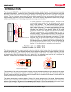
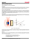
Introduction
The HMR4007 is capable of communicating with a higher-level system through a proprietary communications port
(J1). This port uses a bit-clocked serial protocol for higher speed and higher data integrity than standard serial
protocols. Signal levels are standard TTL compatible. For convenience, a windows-based DLL (dynamic link library)
and sample Visual Basic demonstration program are available from Honeywell that communicates with the sensor
through a PC's parallel port. Interested developers should contact their Honeywell representatives or the factory for
details of the communications protocol and command structure. The communications port can be used independently
or in combination with the analog output described earlier. When used in combination with the analog port, only ONE
port should be used to supply power to the board. Sensor configuration, such as changing the magnet mode from
axial to radial, is available only through the communications port and DDL calls are supplied to support these basic
functions.
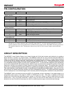
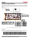
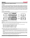
Connector J1 General Description
J1 is a 6-pin header which is wired to a PC parallel port for digital communications with the Honeywell demonstration
DLL software (or other user application) using the following connections:
PC (parallel port) Sensor Board
LPT pin data
direction
J1 pin function color
15 <-- 1 RTS (gray)
13 <-- 2 Data_Out (yellow)
3 --> 3 Data_In (blue)
2 --> 4 CTS (white)
- <> 5 +5-28 VDC (red)
19 <> 6 power gnd (black)
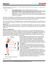
Demonstration Software
Two programs are included with this board to demonstrate its operation.
HMR4007.dll is a dynamic link library that performs low level communications between the host PC's parallel port
and the sensor board to query the current, measured position and support operating mode changes. Several
functions are visible to the user using the following Visual Basic header formats:
Declare Function InitPort Lib "HMR4007.dll" (ByVal ADD As Integer, ByVal TOut As Long) As Integer
Declare Function CurrentPosition Lib "HMR4007.dll" () As Integer
Declare Function SetAxialMode Lib "HMR4007.dll" () As Integer
Declare Function SetRadialMode Lib "HMR4007.dll" () As Integer
Declare Function EnableDAC Lib "HMR4007.dll" () As Integer
Declare Function DisableDAC Lib "HMR4007.dll" () As Integer
The first function, "InitPort", is used to setup the PC's parallel port base address (default is 0x378) and timeout value.
This function must be called before any calls to the operating functions.
The port base address (ADD) is the address of the computer's parallel (printer) adapter and used by the software
as a base address to send and receive data to the sensor card through the parallel port adapter. The value is
passed as a 16-bit integer. Setting this value to -1 re-initializes the port with the previous value (or default value)
retained.
The timeout value (Tout) is used as an internal loop counter to return to the calling program after a fixed time if
for some reason the sensor board fails to respond. A value of 10,000 is the default and works well on a 100MHz
Pentium-class machine. Higher values will be needed for faster machines. The parameter is passed as a 32-bit
long integer. Passing a value of -1 sets the value to the previous (or default) value.
The function returns a 16-bit integer "0" to indicate that the port is active.
Solid State Electronics Center
• www.magneticsensors.com • (800) 323-8295 • Page 7