


iPGSM-COM Commercial Fire Communicator – Installation and Setup Guide
– 4 –
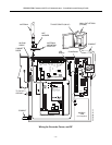
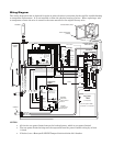
Note: Refer to the diagram on page 5, and to the Wiring Diagram on the inside of the back cover of
this manual for all wiring information.
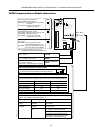
5. Mount the Wall Outlet Box to an un-switched facility power outlet and run a conduit to the cabinet.
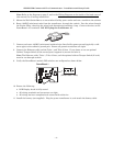
6. Route 16AWG (minimum) wire from the transformer, through the conduit. Pass the wires through
the Ferrite Filter, then loop the wires back through again making a loop. Connect the wires to the
PowerBoost1 AC terminals. DO NOT plug the transformer in.
7. Connect and route 16AWG (minimum) insulated wire from facility power ground (typically a cold
water pipe) to the cabinet's ground post. Ensure all ground connections are tight.
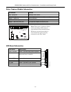
8. Connect the Ethernet cable and the Telco 1 and Telco 2 lines. If you choose to use an optional
Cabinet Tamper Switch (if the control panel supports it) mount and wire it.
Note: The Ethernet cable, Telco 1, Telco 2 lines, and the optional cabinet Tamper Switch (if used)
must be run through conduit.
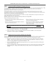
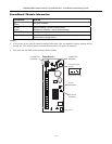
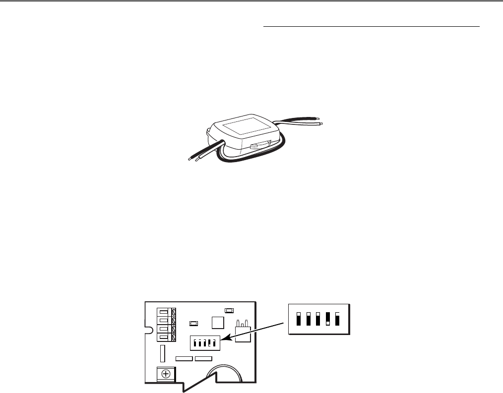
9. Verify the PowerBoost1 module DIP switches are configured as shown below.
iPGSM-COM-008-V0
PowerBoost 1
15
ON
2
3
4
15
ON
2
3
4
(Switch handle = white)
10. Ensure the following:
LED Display board is fully seated.
All wiring terminals and connectors are tight.
All wiring has been completed and secured with cable ties.
11. Install the battery (not supplied). Plug the power transformer in, and attach the battery cable.