


iPGSM-COM Commercial Fire Communicator – Installation and Setup Guide
– 3 –
STEP 3 – Determine the Signal Strength and Select a Location
IMPORTANT - Do Not mount this device outdoors.
When choosing a suitable mounting location, understand that signal strength is very important for proper
operation. For most installations using the supplied antenna, mounting the unit as high as practical, and
avoiding large metal components provides adequate signal strength for proper operation.
You will use the iGSM Communications Module to determine signal strength in order to find a suitable
mounting location.
Note: If the SIM is already activated, the RSSI signal strength indicators will indicate signal
strength.
If the SIM has not been activated, the firmware in the communications module enables it to
communicate with the cellular network towers (without the SIM being activated) so that
signal strength measurements can be determined. In this case, you can display the signal
strength by simultaneously pressing the MODE and TAMPER switches.
1. For this procedure you will need a fully charged 12V battery.
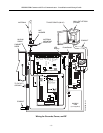
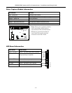
2. Attach the Antenna (see illustration on page 5).
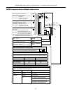
3. Temporarily wire the battery's negative [–] terminal to TB1–4 on the iGSM communications module,
then wire the battery's plus [+] terminal to TB1–2 on the communications module. Wait about one
minute for the module to initialize.
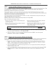
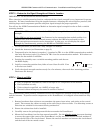
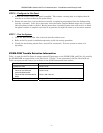
4. Position the assembly near a suitable mounting position and observe
the RSSI display.
5. Look for a mounting position that yields at least 3 bars lit solid. Four
or five bars are better.
6. Verify the signal strength remains steady for a few minutes, then mark that mounting position.
Disconnect the battery.
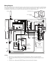
STEP 4 – Mount and Wire
For UL compliant installations, refer to the topic on UL Compliance in this manual.
For Dry/Indoor use only.
Unless otherwise specified, use 18AWG or larger wire.
External cabinet wiring may be routed in conduit if desired.
This communicator comes partially assembled with all the components mounted except the PowerBoost1
and the Antenna. To protect certain components on the PowerBoost1, it is shipped un-mounted but fully
wired.
1. Remove knockouts from cabinet to accommodate the power input wires, and wiring to the control
panel. Then mount the cabinet securely to the wall using 4 screws or bolts. Use mounting screws or
bolts that are suitable for the material being anchored to.
2. Ensure the cabinet door lock is installed.
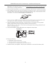
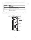
3. Carefully remove the packaging material that surrounds the PowerBoost1.
4. Mount the PowerBoost1 on the three unused standoffs. Use the plastic screw
(prevents shorting)
to secure the upper right corner of the PowerBoost1 and the two metal screws and lock washers to
fasten the left side of the circuit board. Ensure the two lock washers are between the circuit board
and the head of the two metal screws.
3 BARS MIN.
GYGGRY
7845i-GSM-025-V0