


T7351 COMMERCIAL PROGRAMMABLE THERMOSTAT
63-2666—03 6
a
Factory jumper between RC and RH for systems with one
transformer.
b
For changeover functional details, see Operation section.
c
HC connection is not needed when using a TR23-H sensor.
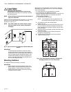
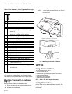
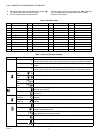
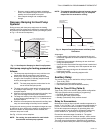
Mounting Thermostat on Subbase
(Fig. 7)
With the subbase installed, mount the thermostat:
1. Engage the tabs at the top of the thermostat and sub-
base.
2. Swing the thermostat down.
3. Press the lower edge of the case to latch.
NOTE: To remove the thermostat from the wall, first pull
out at the bottom of the thermostat; then
remove the top.
Fig. 7. Mounting Thermostat on Subbase.
SETTING
Using Thermostat Keys
The thermostat keys are used to:
• set current time and day,
• program times and setpoints for heating and cooling,
• override the program temperatures,
• display present setting,
• set system and fan operation,
• perform simple configuration.
NOTE: Refer to Fig. 8 for keypad information.
Setting Temperature
Refer to Table 2 for the default temperature setpoints. See
Programming section for complete instructions on changing
the setpoints.
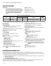
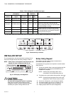
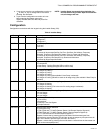
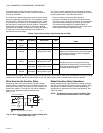
Table 3. T7351 Subbase for Three-stage Heat, Three-stage
Cool Systems.
Terminal
Description
Conventional
Heat Pump
RC
a
RC
a
24 VAC Cooling transformer.
RH
a
RH
a
24 VAC Heating transformer.
X X Common.
aux aux Auxiliary relay.
W1 O/B Conventional: Stage 1 heating relay.
Heat Pump: Changeover relay for heating (B) or
cooling (O)
b
.
W2 W1 Conventional: Stage 2 heating relay.
Heat Pump: 1st Stage auxiliary heat relay.
Y1 Y1 Conventional: Stage 1 cooling relay.
Heat Pump: Stage 1 compressor relay.
Y2 Y2 Conventional: Stage 2 cooling relay.
Heat Pump: Stage 2 compressor relay.
AS AS Discharge Air Sensor connection (1).
AS AS Discharge Air Sensor connection (2).
OS OS Outdoor Air Sensor connection (1).
OS OS Outdoor Air Sensor connection (2).
G G Fan relay.
T3 T3 TR20 Series Remote Sensor connection (1).
T4 T4 TR20 Series Remote Sensor connection (2).
T5 T5 TR20 Series Remote Sensor connection (5).
T6 T6 TR20 Series Remote Sensor connection (9).
T7 T7 TR20 Series Remote Sensor connection (7).
W3 W2 Conventional: Stage 3 heat or stage 4 cool relay.
Heat Pump: 2nd Stage auxiliary heat relay.
Y3 — Conventional: Stage 3 cooling relay.
HS HS Humidity Sensor connection (signal: 0-10 Vdc).
TR23-H connection (11)
HC HC
Humidity Sensor connection (common).
c
HP HP Humidity Sensor connection (power). TR23-H
connection (12)
M M Motion Sensor connection (1).
M M Motion Sensor connection (2).
M19609
B.
PRESS LOWER EDGE OF CASE TO LATCH.
A.
ENGAGE TABS AT TOP OF THERMOSTAT AND SUBBASE OR WALLPLATE.