


T7351 COMMERCIAL PROGRAMMABLE THERMOSTAT
19 63-2666—03
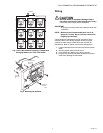
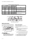
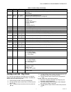
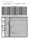
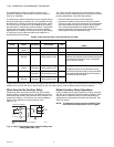
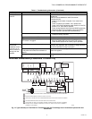
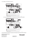
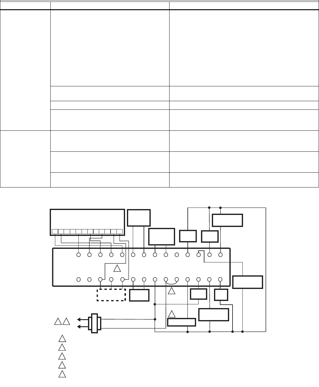
WIRING DIAGRAM (FIGURES 14 AND 15)
Fig. 14. Typical Hookup of T7351F2010 in Three-Stage Heat and Three-Stage Cool Conventional System with One
Transformer.
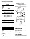
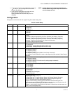
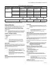
Cooling will not
come on.
No power to the thermostat. Check that X terminal is connected to the system
transformer.
Check for 24 Vac between X and RC terminals.
If missing 24 Vac:
• Check if circuit breaker is tripped; if so, reset circuit
breaker.
• Check if system fuse is blown; if so, replace fuse.
• Check if the HVAC equipment power switch is in the Off
position; if so, set to the On position.
• Check wiring between thermostat and HVAC equipment.
Replace broken wires and tighten loose connections.
If 24 Vac is present, proceed with troubleshooting.
Thermostat minimum off time is activated. • Wait up to five minutes for the system to respond.
• Configure cooling response.
System selection is set to Off or Heat. Set system selection to Cool or Auto.
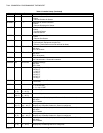
DAT low limit has been reached, or
OAT lockout is engaged.
• If the setpoints are correct, do nothing.
• Adjust or disable DAT low limit and/or OAT lockout.
• Check HVAC equipment to ensure proper operation.
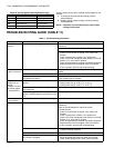
System indicator
(flame: heat,
snowflake: cool) is
displayed, but no
warm or cool air is
coming from the
registers.
The call for heat or cool is not yet given. Check if any stage indicators (dots next to the system
indicator) are displayed. With no display of stage indicators,
no call for cool/heat via relay is yet given.
Conventional heating equipment turns the fan
on only after the furnace has warmed to a
setpoint.
Wait one minute after seeing the on indicator and then
check the registers.
Heating or cooling equipment is not operating. Verify operation of heating or cooling equipment in Test
Mode.
Table 11. Troubleshooting Information. (Continued)
Symptom Possible Cause Action
POWER SUPPLY. PROVIDE DISCONNECT MEANS AND OVERLOAD PROTECTION AS REQUIRED.
ENSURE TRANSFORMER IS SIZED TO HANDLE THE LOAD.
HEAT/COOL SYSTEMS WITH ONE TRANSFORMER REQUIRE THE FACTORY-INSTALLED JUMPER.
USE ECONOMIZER INSTRUCTIONS FOR INSTALLATION DIRECTIONS.
WHEN USING THE TR23-H FOR HUMIDITY SENSING THERE IS NO NEED TO WIRE HC TERMINAL
BECAUSE THE T3 TERMINAL IS INTERNALLY TIED TO HC, WHICH IS ALSO TIED TO TERMINAL 1
COMMON AT THE SENSOR.
1
M29255
2
3
2
3
4
RCX
SUBBASE
W1 GY1
W3/Y4 Y3 W2 Y2
AUXRH
T5 T6 T7 T4 T3
DISCHARGE
AIR
SENSOR
OUTDOOR
AIR
SENSOR
MOTION
SENSOR
HUMIDITY
SENSOR
M
OSOS ASAS
MHC HPHS
1
L1
(HOT)
L2
COMPRESSOR
CONTACTOR 1
COMPRESSOR
CONTACTOR 2
HEAT
RELAY 1
FAN
RELAY
HEAT
RELAY 2
COMPRESSOR
CONTACTOR 3
HEAT
RELAY 3
TR23-H REMOTE SENSOR
9
8
76
5
4
3
21
10
11
12
GND
SENSOR
SET PT
LED
BYPASS
5
5
4
ECONOMIZER