T7351 COMMERCIAL PROGRAMMABLE THERMOSTAT
63-2666—03 14
T7351 Relay Logic
All T7351 model thermostats contain at least four switching
relays. In conventional applications, the relays control first
stage cooling, first stage heating, fan, and auxiliary. In heat
pump applications, the relays control the heat pump
compressor, changeover, fan, and emergency heat.
O/B Terminal for Heat or Cool
Changeover
The O/B terminal controls heat pump changeover. The default
operation is for the terminal to be powered when calling for
heat (or while the most recent call was for heat). This
corresponds to a typical B terminal.
NOTE: The O/B terminal can be configured to operate as
a typical O terminal (powered on call for cool).
Emergency Heat
With the system set for Em Heat, auxiliary heat serves as
stage one; compressor stages are locked off. The fan cycles
with the auxiliary heat.
Equipment Protection
As part of the operational sequence, the T7351
microprocessor incorporates cycle rate, and minimum on and
off times for all heating and cooling stages. This extends
equipment life as it prevents rapid cycling of equipment.
NOTE: Minimum on and off times are fixed.
Cycle Rates
The thermostat control algorithm maintains the temperature by
cycling stages of heating or cooling to meet setpoint. Cycle
rates, in cycles per hour (cph) are set in the installer setup.
NOTE: Defaults are: heat: 6cph, cool: 3cph.
P+I+D Control
The T7351 microprocessor-based control requires that the
user understands temperature control and thermostat
performance. A conventional electromechanical or electronic
thermostat does not control temperature precisely at setpoint.
Typically, there is an offset (droop) in the control point as the
system load changes. This is a phenomenon that most people
in the industry know and accept.
IMPORTANT
• P+I+D (Loop Tuning) parameters are optimized for
proper operation of a vast majority of HVAC systems.
Only when completely certain of necessary and
proper changes should you alter these values.
• Improper changes result in poor system performance
and equipment problems such as compressor short
cycling. Other problems include wide swings in space
temperature and excessive overdriving of modulating
outputs.
All adjustments to Loop Tuning parameters should be gradual.
After each change, allow the system to stabilize to accurately
observe the effects of the change. Then, as needed, make
further refinements until the system operates as desired.
If adjustment of PID parameters is required, use the following:
NOTE: In the items that follow, the term “error” refers to
the difference between the measured space tem-
perature and the current actual space tempera-
ture setpoint:
—The Throttling Range (TR), also called Proportional Gain,
determines the impact of the error on the output signal.
Decreasing TR amplifies the error effect; that is, for a given
error, smaller TR causes higher output signal.
—The Integral Time (IT), also called Integral Gain,
determines the impact of the error-over-time on the output
signal. Error-over-time has two components making up its
value: amount of time the error exists; and size of the error.
The higher the IT, the slower the control response. In other
words, a decrease in IT causes a more rapid change to the
output signal.
—The Derivative Time (DT), also called Derivative Gain,
determines the impact of the error rate on the output signal.
The error rate is how fast the error value changes. It can
also be the direction the space temperature is going, either
toward or away from the setpoint, and its speed—rapid or
slow. A decrease in DT causes, for a given error rate, a
greater effect on output signal.
Recovery Ramping Logic
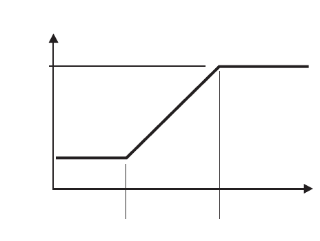
The T7351 incorporates a ramping feature that gradually
changes the space setpoints. During recovery operation, the
setpoint changes at a rate in degrees per hour depending on
the outdoor air temperature. If there is no outdoor air
temperature sensor available, the minimum ramp rate is used.
When recovering in heating, the control point raises gradually,
maximizing the use of the more economical first stage heat to
bring the sensed temperature to the desired comfort setpoint.
This minimizes using the typically more expensive later
stage(s) of heat.
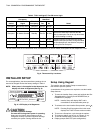
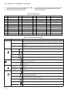
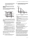
NOTE: See Fig. 10 for a pictorial representation of the
heat ramp rate determination.
Recovery Ramping for Conventional
Systems
Fig. 10. Heat Setpoint Ramping for Conventional Systems.
NOTES:
HEAT RECOVERY
RAMP RATE
(DEGREES/HOUR)
MaxHtRamp
MinHtRamp
OaTempMinHtRamp OaTempMaxHtRamp
OUTDOOR AIR
TEMPERATURE
M10109A


