


T7351 COMMERCIAL PROGRAMMABLE THERMOSTAT
5 63-2666—03
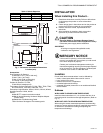
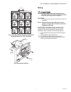
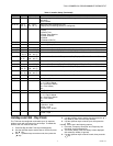
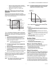
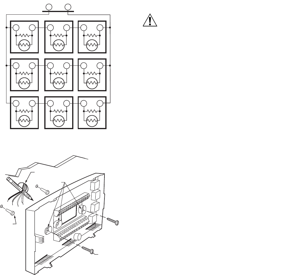
Fig. 5. Nine TR21 Sensors Providing a Temperature
Averaging Network for T7351 Thermostat.
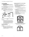
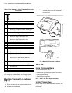
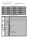
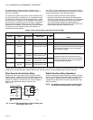
Fig. 6. Mounting the Subbase.
Wiring
CAUTION
Electrical Shock or Equipment Damage Hazard.
Can shock individuals or short equipment circuitry.
Disconnect power supply before installation.
IMPORTANT
All wiring must comply with local electrical codes and
ordinances.
NOTE: Maximum (and recommended) wire size is 18-
gauge (ø 1.02 mm). Do not use wire smaller than
22-gauge (ø 0.644 mm).
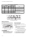
Follow equipment manufacturer wiring instructions when
available. Refer to the Wiring Diagram section for typical
hookups. A letter code is located near each terminal for
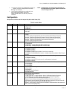
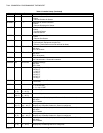
identification. Refer to Tables 3 for terminal designations.
1. Loosen subbase terminal screws and connect system
wires.
2. Securely tighten each terminal screw.
3. Push excess wire back into the hole in the wall.
4. Plug the hole with nonflammable insulation to prevent
drafts from affecting the thermostat.
M29257
TT
TR21
TT
TR21
TT
TR21
TT
TR21
TT
TR21
TT
TR21
T
T
TR21
T
T
TR21
TT
TR21
T4 T3
SUBBASE
WIRES THROUGH WALL
WALL
ANCHORS
(2)
M19608
MOUNTING
HOLES
MOUNTING
SCREWS