


T7351 COMMERCIAL PROGRAMMABLE THERMOSTAT
15 63-2666—03
— Recovery ramping applies between scheduled
heat or cool setpoint changes from not occupied to
standby and not occupied to occupied.
— Other setpoint changes use a setpoint step
change.
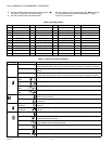
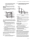
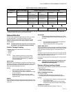
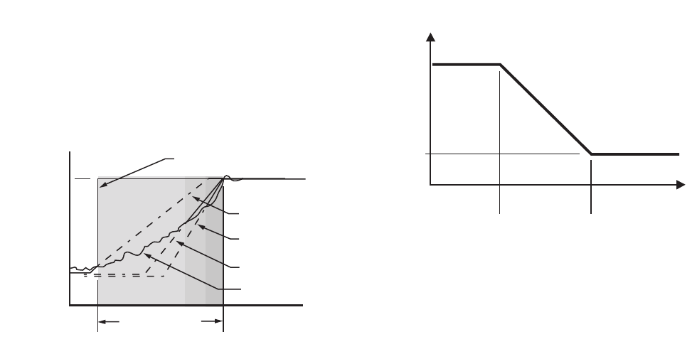
Recovery Ramping for Heat Pump
Systems
During recovery with heat pump equipment, the heating
setpoint is split into a heat pump setpoint for compressors, and
two auxiliary heat setpoints for the auxiliary heat stages. (Refer
to Fig. 11 for the various setpoints.)
Fig. 11. Heat Setpoint Ramping for Heat Pump Systems.
Heat pump ramping for heating proceeds as
follows:
1. The heat pump setpoint begins to ramp until the room
temperature and the compressor ramp intersect.
2. At this point, the heat pump setpoint performs a step
change to the Occupied (or Standby) setpoint and all
auxiliary heat stages are disabled.
NOTE: The heat pump setpoint remains here for the
rest of the Not Occupied period.
3. The stage one auxiliary heat ramp is calculated based
on a steeper slope starting 1° F (0.5° C) below the not
occupied setpoint.
4. When the room temperature intersects this auxiliary heat
ramp, the first stage of auxiliary heat is enabled.
5. The stage two auxiliary heat ramp is calculated based on
an even steeper slope starting 2° F (1° C) below the not
occupied setpoint.
6. When the room temperature intersects this auxiliary heat
ramp, the second stage of auxiliary heat is enabled.
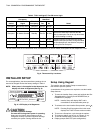
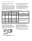
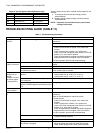
During the cool recovery period, the setpoint changes at a rate
in degrees per hour relative to the outdoor air temperature. If
there is no outdoor air temperature sensor available, the
minimum ramp rate is used.
See Fig. 12 for the various setpoints.
NOTE: For cooling, the same method is used in both
conventional and heat pump systems.
NOTE: The setpoint used during the cool recovery period
is similar to the heat mode in Fig. 10, except the
slope of the line reverses for cooling.
Fig. 12. Setpoint Ramping Parameters with Ramp Rate
Calculation.
Advantages:
• Comfort setting is achieved at the programmed time and
maintained regardless of weather conditions; occupants are
comfortable.
• Drafts from low-temperature discharge air are minimized
during Occupied periods.
• Use of the more economical first stage of heat is maximized
during recovery, minimizing use of the expensive later heat
stage(s).
• Comfort and energy savings can be achieved in both
heating and cooling.
• Heat cycling reduced, extending equipment life.
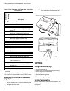
Auxiliary Relay
The auxiliary relay can be used with a variety of controls:
• Time-of-day (TOD).
• Economizer minimum position control.
• Dehumidification (see Dehumidification section).
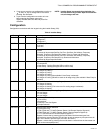
Relay for Time-Of-Day (Table 8)
Time-of-day (TOD) is the Auxiliary Relay default configuration.
TOD logic operates strictly according to programming:
— Occupied: Relay contacts closed.
— Not Occupied: Relay contacts open.
— Standby (Scheduled): Relay contacts closed.
Relay for Economizers
Mechanical cooling is often used with outside temperatures in
the 50° F (10° C) to 60° F (16° C) range and humidity below 50
percent. In central and northern climates, hundreds of hours
fall into this temperature category. By permitting 80 to 100
percent outside air into the system, mechanical cooling may
not be needed at all, particularly during Spring and Fall.
Economizers take advantage of outside air. The typical
economizer consists of an outside air damper, motor, outdoor
air changeover control and a minimum position potentiometer.
The motor controls the dampers. Suitability of the outside air
for cooling is determined by the outdoor air changeover control.
AUX HEAT
STAGE 1 RAMP
NORMAL
RECOVERY RAMP
OCCUPIED
SETPOINT
NOT OCCUPIED
SETPOINT
M19877
RECOVERY TIME
OCCUPIED
TIME
AUX HEAT
STAGE 2 RAMP
HEAT PUMP SETPOINT
(FOR COMPRESSORS)
SPACE
TEMPERATURE
COOL RECOVERY
RAMP RATE
(DEGREES/HOUR)
MaxClRamp
MinClRamp
OaTempMinClRamp OaTempMaxClRamp
OUTDOOR AIR
TEMPERATURE
M10111A